There are several ways to couple multiple inductors together:
Using the INDUCTOR_COUPLING componentUse this method if you already placed and configured standard inductors in your schematic:
- Select Place » Component from the main menu.
- Select Basic in Group.
- Select the Transformer family.
- Find and place the INDUCTOR_COUPLING component into the schematic.
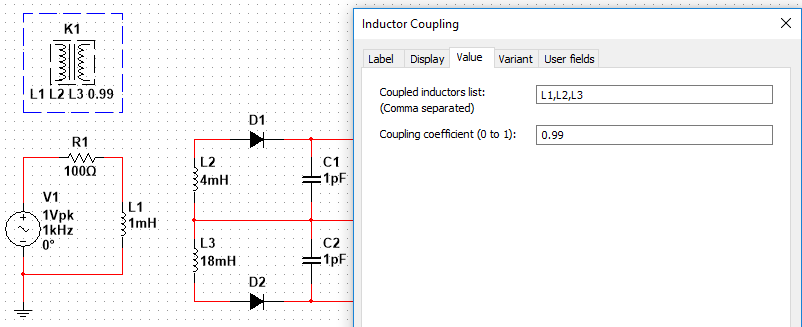
- Double-click the INDUCTOR_COUPLING, go to the Value tab, enter the inductors to couple into the Coupled inductors list: (Comma separated) field and put the desired value into the Coupling coefficient (0 to 1) field.
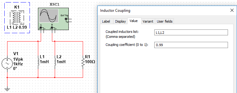
This method can also be used to couple more than two inductors.
Refer to Inductor Coupling in the
NI Multisim™ Help for further details.
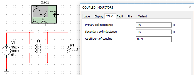
Using the COUPLED_INDUCTORS componentThe second method is to use
COUPLED_INDUCTORS component:
- Select Place » Component from the main menu.
- On the left side of the Select a Component dialog, select Basic from the Group drop-down menu.
- Below, select the Transformer family.
- Find the COUPLED_INDUCTORS component and place it into the schematic.
- Double-click the COUPLED_INDUCTORS and enter the Primary and Secondary coil inductance values, as well as the Coefficient of coupling.
Refer to Coupled Inductors in the NI Multisim™ Help for information on the component's parameters.
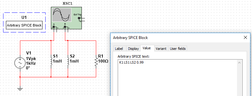
Using the ARBITRARY_SPICE_BLOCK componentUsing the
ARBITRARY_SPICE_BLOCK component, you can add additional SPICE commands to the SPICE netlist generated by Multisim in the background as follows:
- Select Place » Component from the main menu.
- On the left side of the Select a Component dialog, select Basic from the Group drop-down menu.
- Beneath, select BASIC_VIRTUAL as Family.
- Locate the ARBITRARY_SPICE_BLOCK in the Component list and place it somewhere on your schematic by clicking OK.
- Double-click the newly-placed ARBITRARY_SPICE_BLOCK on your schematic, go to the Value tab, and put SPICE commands into the Arbitrary SPICE text area according to this scheme:
K<coupling name> <ID Induction 1> <ID Induction 2> <Coupling Coefficient>
Example: K1 LS1 LS2 0.99
Explanation:
- Multisim™ adds an additional letter L to the RefDes of an inductive component to create its ID. If an inductor's RefDes is e.g. S1 on the schematic, then its ID is LS1. Therefore, the example code above couples the two inductors S1 and S2 with a coupling coefficient of 0.99.
- Add more IDs to the command in case you want to couple more than two inductors (like K2 LS1 LS2 LL5 LT17 0.99).
- Use distinct names, e.g. consecutive numbers as coupling name.
Refer to Coupled (Mutual) Inductor in the Multisim™ Help or any SPICE manual for more information how to derive the coupling coefficient.
Additional Information
The
Inductor_Advanced is not compatible with Inductor Coupling and can cause the error:
Warning: Inductor-voltage source loop found: L1, V1. Since inductors are short-circuited during the DC bias point calculation, the loop will cause a problem for most analyses. Consider breaking the loop by inserting a small series resistor