To use the Counter Input channels on a PXIe-6612 for pulse measurement in VeriStand, it requires the presence of a DAQ card in the chassis that can supply a sample clock on the RTSI/PXI_TRIG 0 line. This example will be using PXIe-6345 to export the clock.
VeriStand Configuration
- Open VeriStand System Explorer.
- Make sure that your hardware has been discovered in System Explorer. If not, use the Hardware Discovery Wizard.
- On the Chassis page, export the PXIe-6345 clock by configuring to export the ai/SampleClock on Default/RTSI/PXI_Trig 0 so that it is available for the CI channel to use.
- Right click on your PXI-6621, then select Add Channels.
- Select channel type to add as CI and select measurement type as Pulse Measurement, then make sure that Sample Clock Source set as RTSI/PXI_Trig 0.
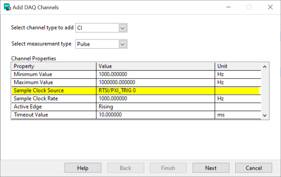
- Select the CI channels to be added, for example like the picture below.
- Create a new screen on the VeriStand project and drag the counter to view the result for the Frequency and Duty Cycle, then deploy the project in your RT target.