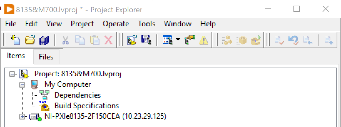
1. Create a LabVIEW project, add a Real-Time PXI controller to the network, and connect to it.
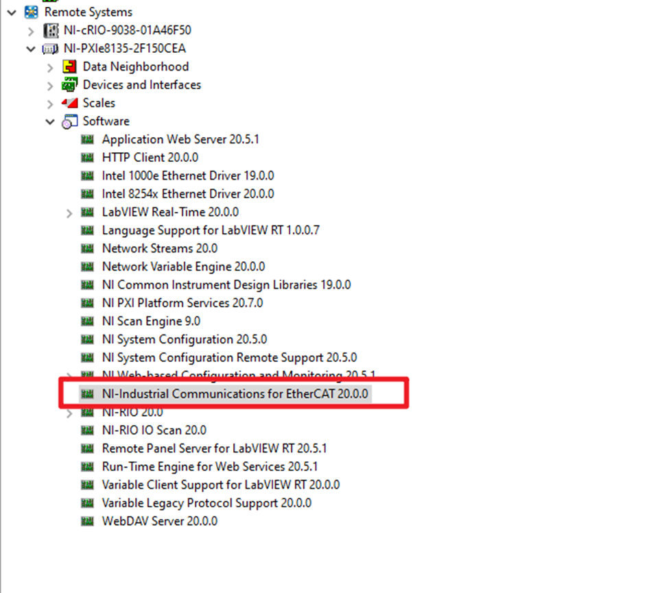
2. Make sure the NI-Industrial Communications for EtherCAT driver has been well installed on the PXI RT controller.
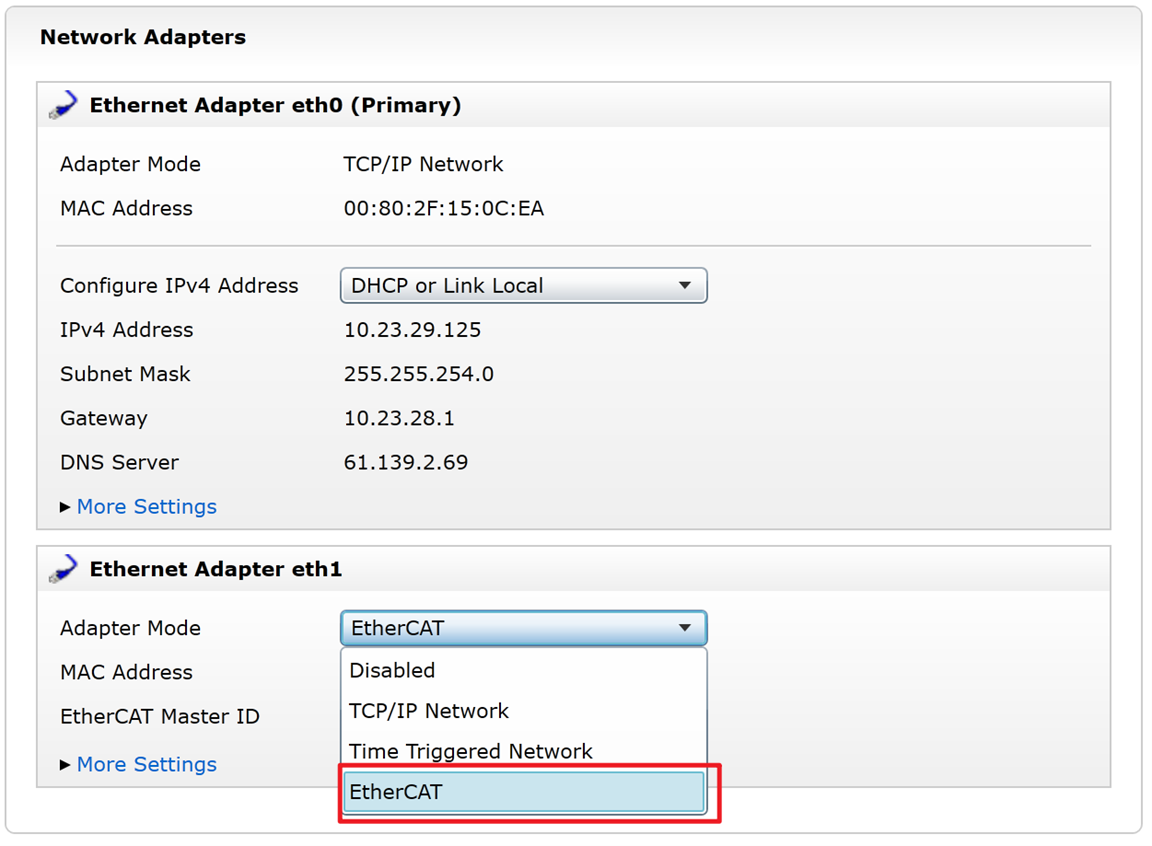
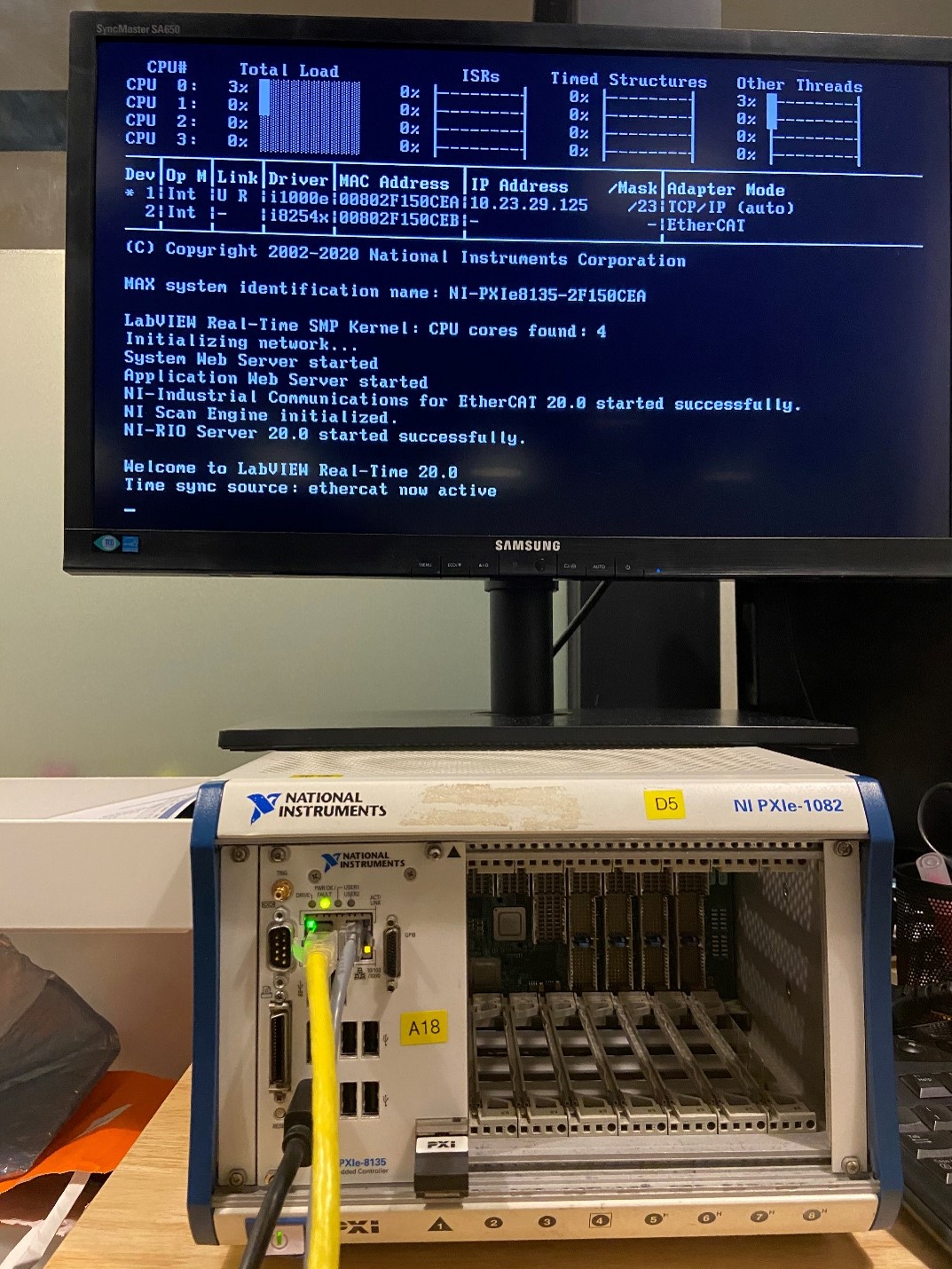
3. In NI MAM, set the PXI controller Ethernet Adapter eth1 as EtherCAT. If you cannot find the EtherCAT selection, you need to check your drivers and software environment.
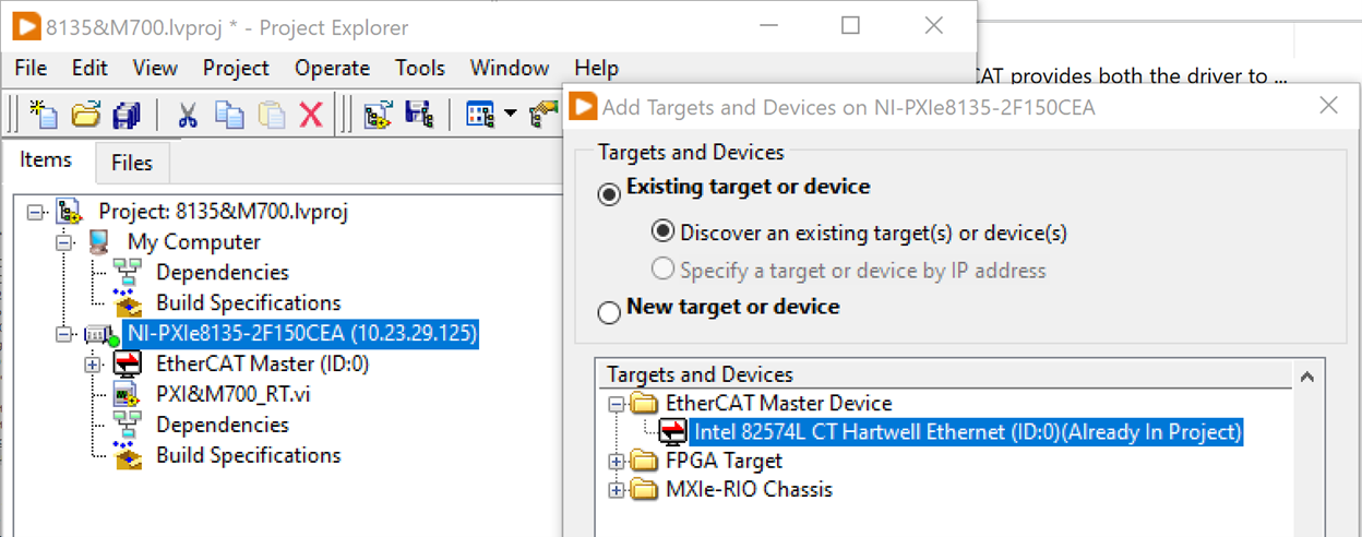
4. Add your PXI EtherCAT interface resource to the project. (In this case, Intel 82574L)
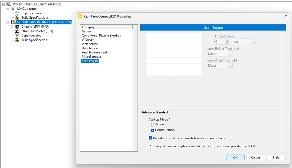
5. Switch the Scan Engine Startup Mode to Configuration.
6. Import the Nidec Unidrive M700 XML file into LabVIEW. The firmware is provided by the drive manufacturer and must be compatible with the Industrial Communications for EtherCAT driver. Check with your drive vendor to confirm the correct version.
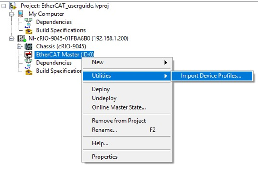
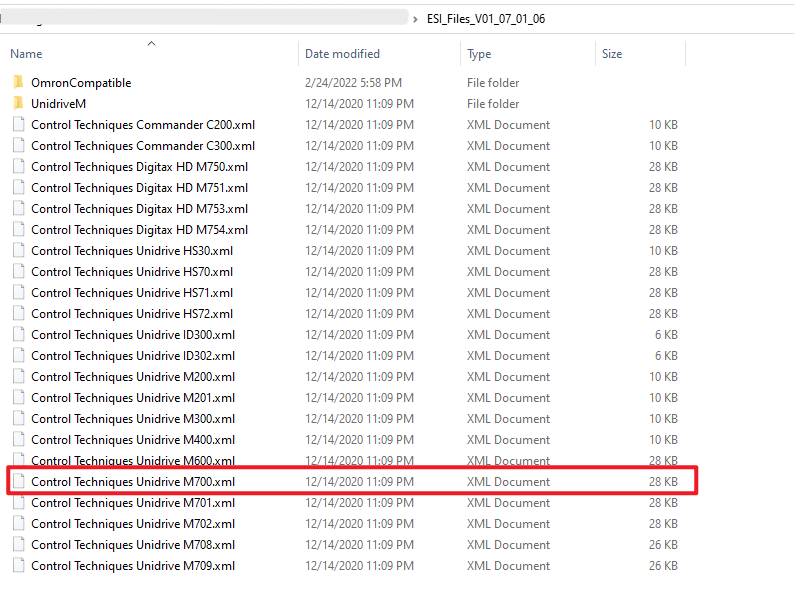
Note: Do not rename the XML file, as this may cause an unknown error.
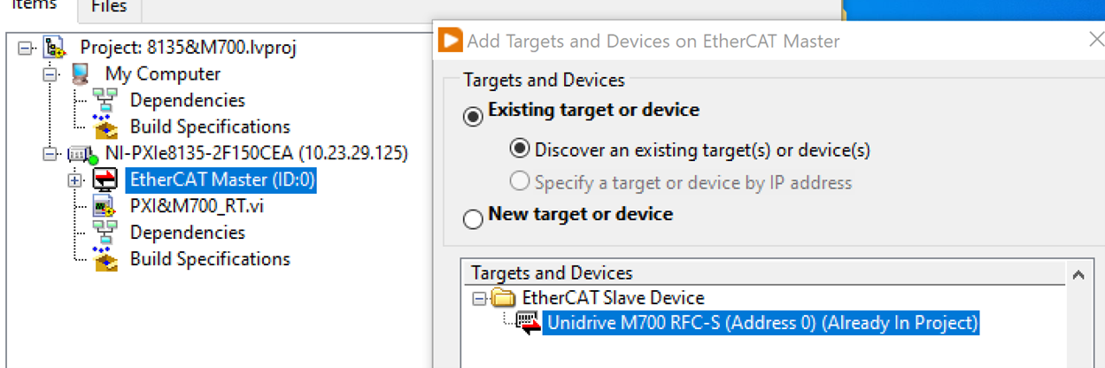
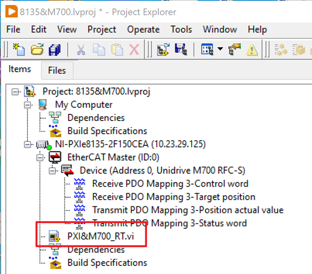
After successfully importing the profile(s), LabVIEW now can detect the existing EtherCAT slave device(s) connected to the PXI controller and will automatically import the PDOs to the project tree.
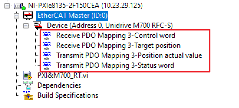
If you would like to change opened I/O in LabVIEW, you need to revise the XML file. It is not recommended to change the XML files, so it's best to reach out to an expert on this drive. To change the PDOs on your own, you can refer to the article Change PDO Mappings for a Third Party EtherCAT XML File.
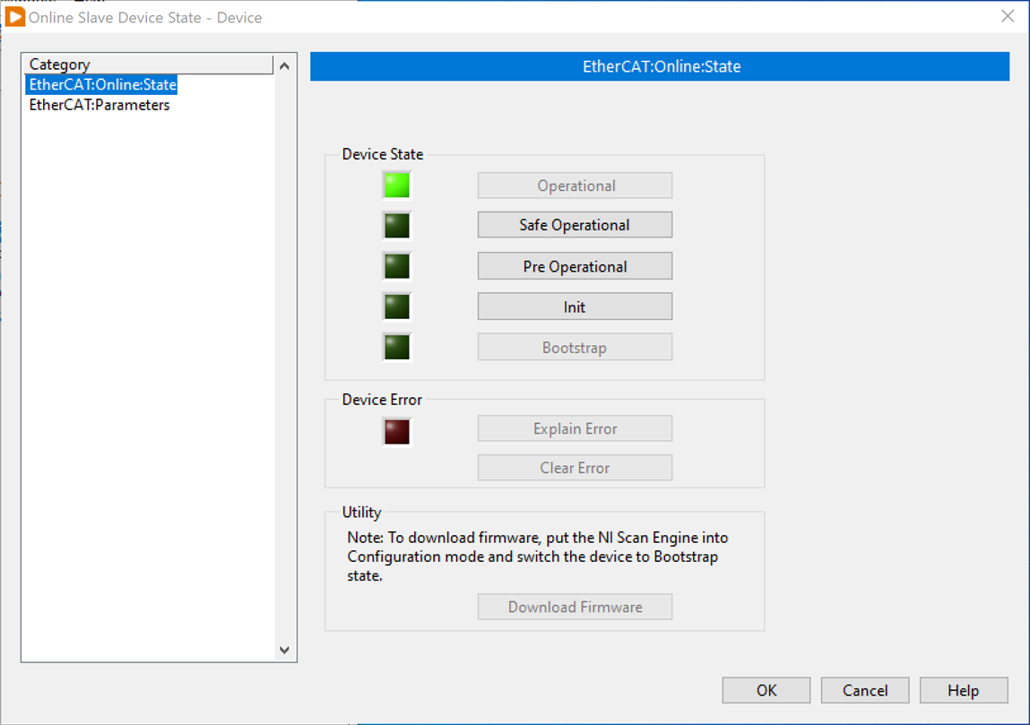
7. To check for the Online state and parameters of the EtherCAT Slave device (the drive), right-click the Slave device in LabVIEW project and select Online Slave Device State.
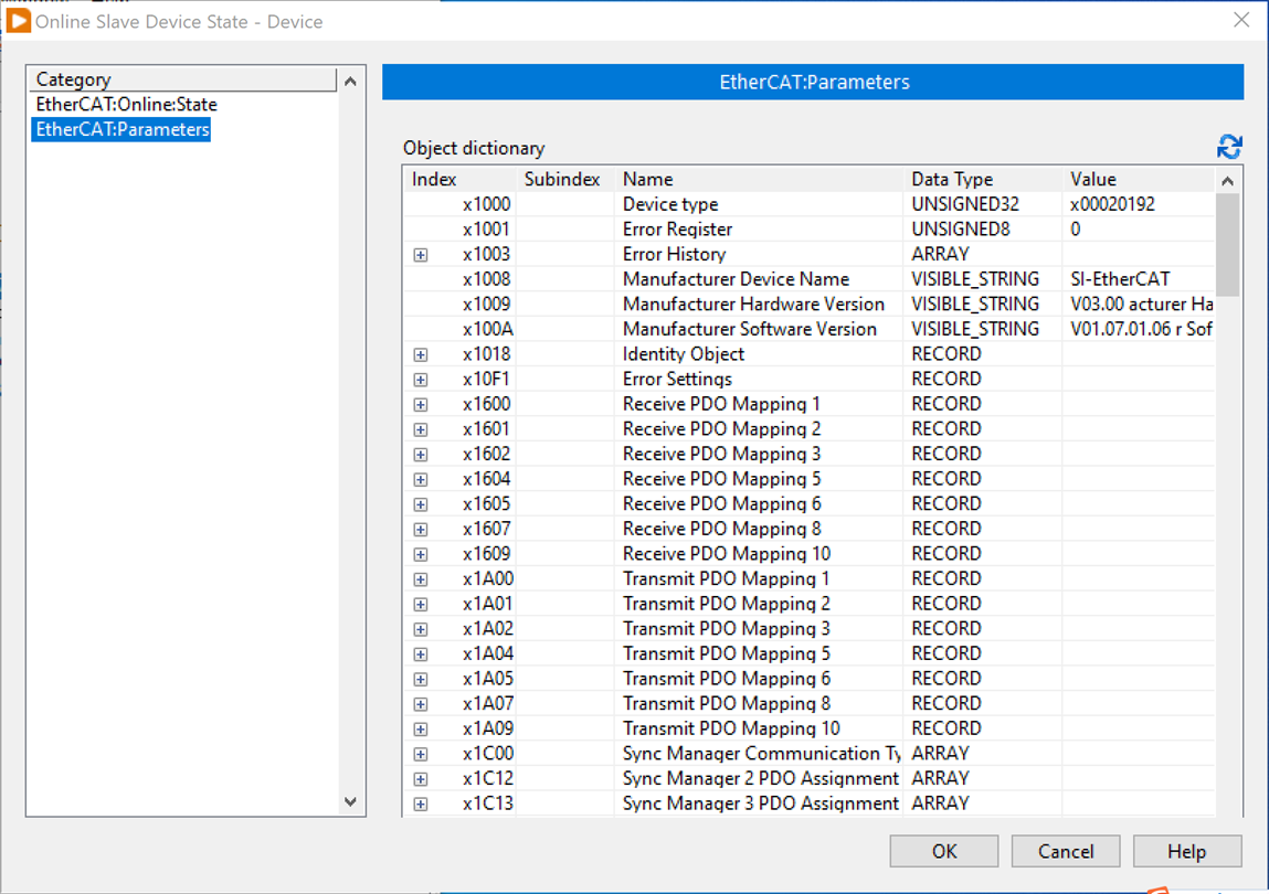
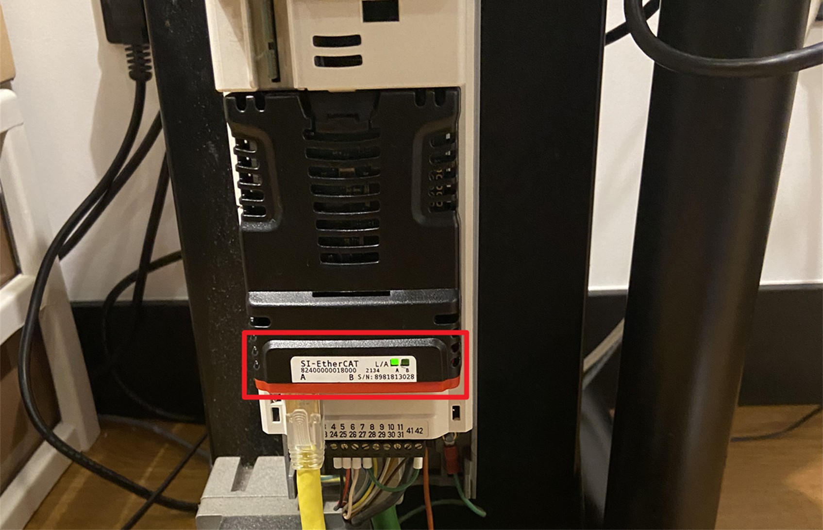
Under normal communication, the green light of the Ethernet network port will continue to blink, if it is steady green on it is successful connected but not established data communication.
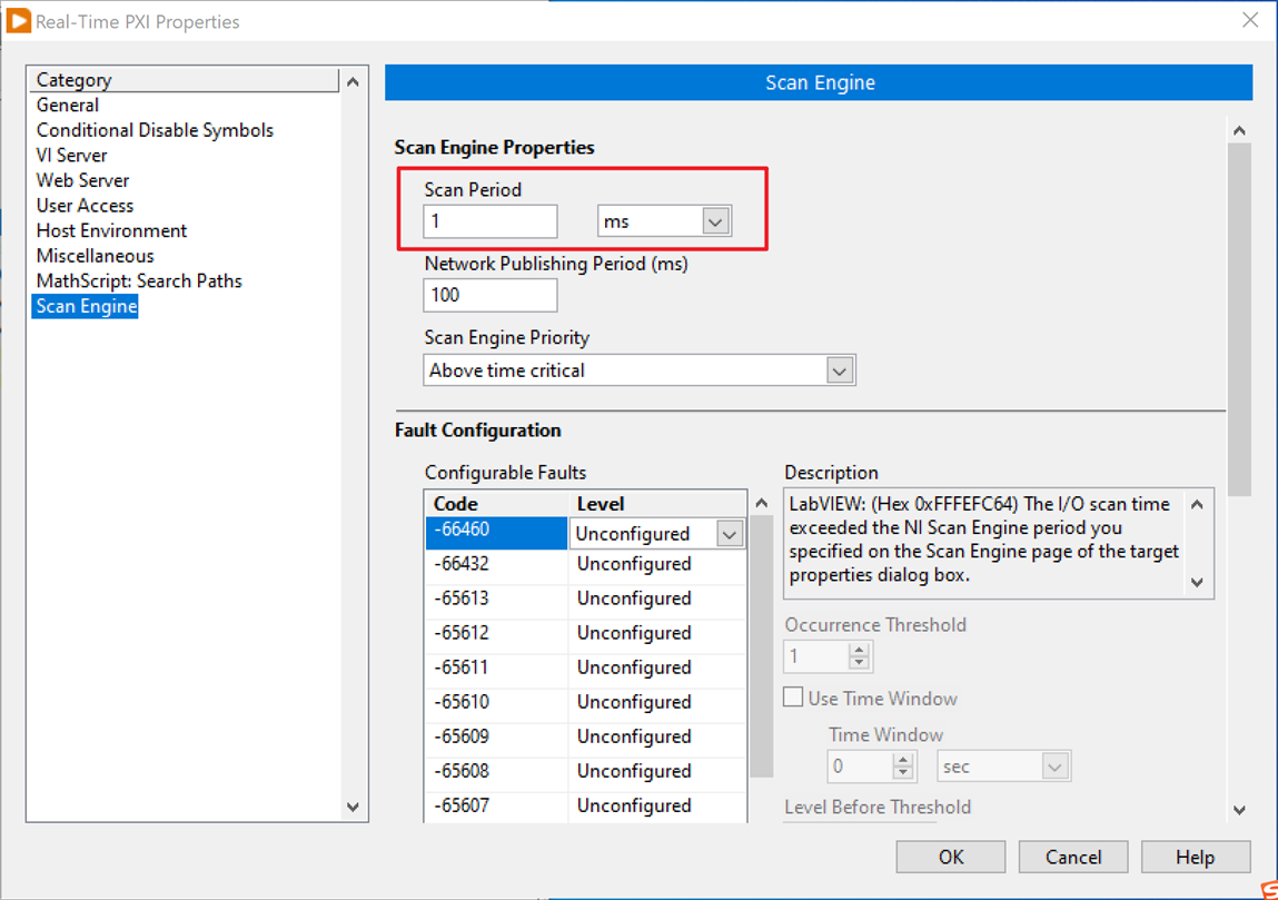
8. In the Real-Time target's properties, configure the EtherCAT Slave device's Distributed Clock to be same as the NI Scan Engine period. In this case, the Scan Engine's period is 1ms.
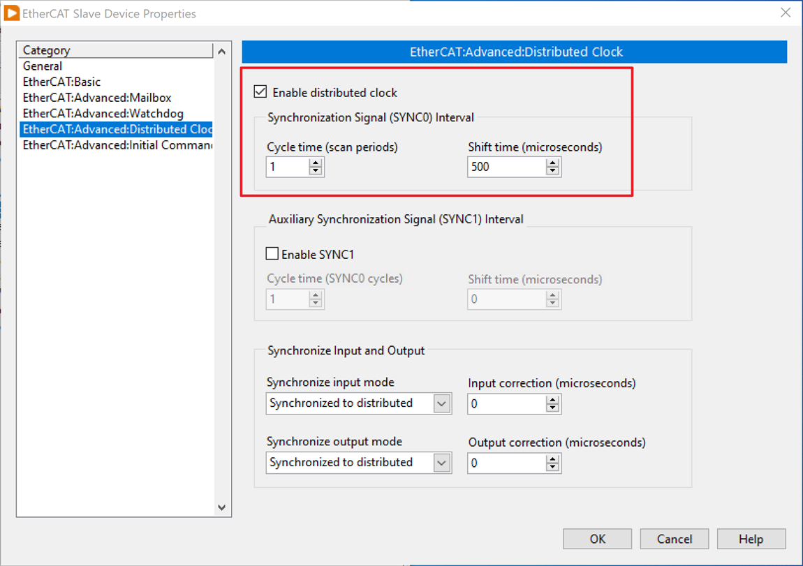
9. In the EtherCAT Slave Device Properties, enable the Distributed Clock and set Shift Time as half of the Scan period.
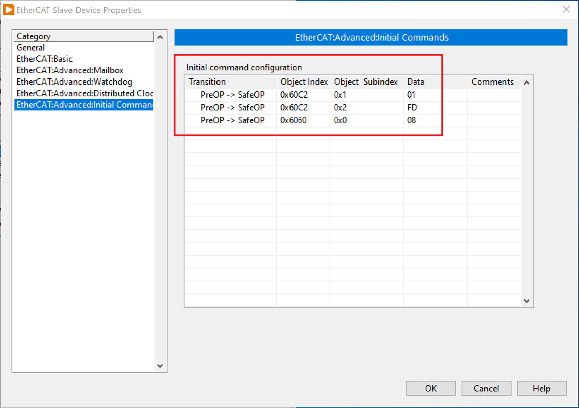
10. Configure some Initial Commands for the Slave device to make sure it works as expected in pre-operational states. In this case, you need to configure 0x60C2, subindex 0x1 as 01, 0x2 as FD. Different hardware has different configuration requirements, ask your drive vendor for specific instructions.
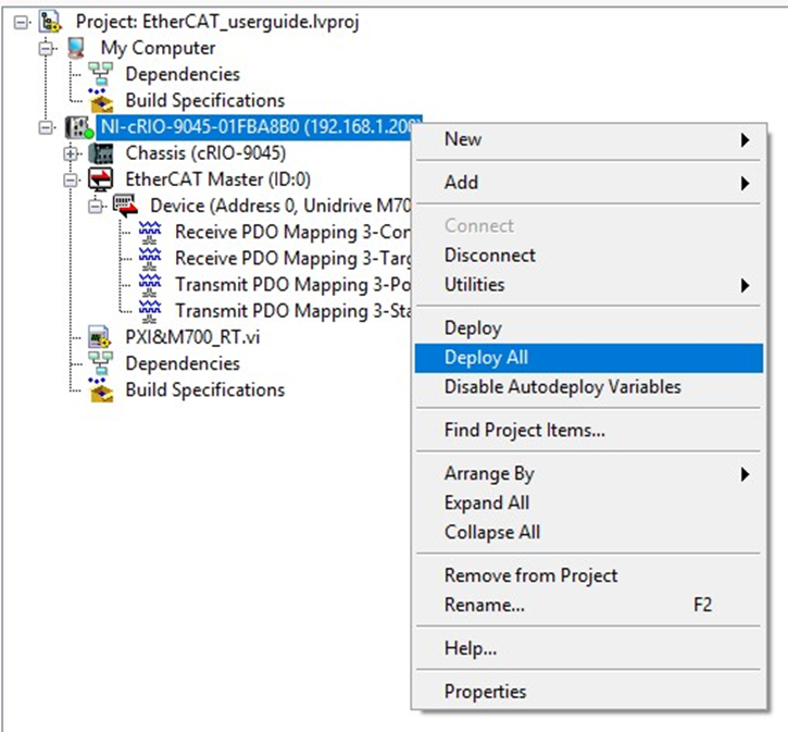
11. Right-click the RT target and choose Deploy all.
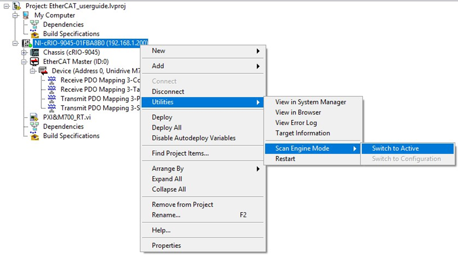
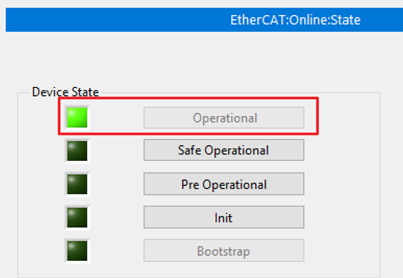
12. Before running your VI code, switch the Scan Engine Mode from Configuration to Active. Check that the device has entered the Operational state in the Online Slave Device State window.
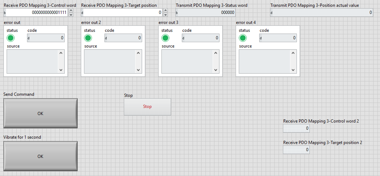
13. Run your LabVIEW RT VI developed based on the opened PDOs of the drive. Use the attached code as a reference.
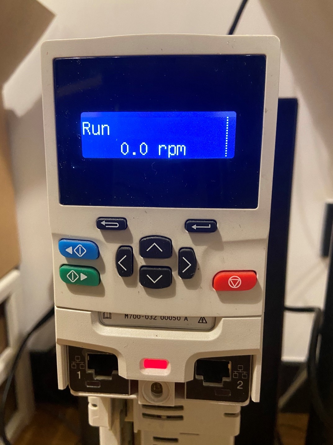
14. Send 0110B, 0111B, 1111b control words in sequence to start the drive. The drive's panel will display "Run."
15. Modify the value of the Target Position. It can be found that in Position mode. The motor shaft rotates as the value changes.
16. Refer to the EtherCAT communication documentation from the drive vendor to check the meaning of the Status Word IO return values, which correspond to the current Status of the drive.
17. Position Actual Value returns the value of the motor encoder. A different value will be returned when the Position of the shaft changes.