This article assumes that a Digital Pattern Editor project (.digiproj) file is already in use and that a Pin Map, Specifications, Timing and Levels file has been created.
To learn about how to get started with a Digital Pattern Editor project, refer to Getting Started with Digital Pattern Editor.
1. From the Project Files Panel, create a new Source Waveform.
- Right-click the Waveforms folder and select New >> Source Waveform.
2. Specify a name for the waveform in the
Source Waveform Name section.
3. Complete the fields in the
Source Waveform Configuration section. Refer to
Source Waveform Configurations for more details.
- Ensure that a Pin or Pin Group is specified in the Pins/Pin Groups field.
4. Specify the samples to drive on the pins.
- An example of a fully configured Source Waveform is shown below:
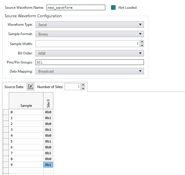 Note:
Note: The Source Waveform shown has been configured as a Serial Waveform consisting of 10 samples. The samples are displayed in Binary format and have a Sample Width of 1.
5. Create a Pattern file.
- From the Project Files panel, right-click the Patterns folder and select New >> Pattern.
6. Specify a name for the Pattern in the
Pattern Name field.
7. Add a row to the Pattern to start sourcing a waveform.
- Assign a Time Set for the row using a suitable Time Set defined in the Timing sheet.
- Set the Opcode to source_start(waveform_name) where "waveform_name" indicates the name assigned to the Source Waveform.
8. Add a row to the Pattern that waits for 3 µs.
- A minimum delay of 3 µs is required between the source_start() Opcode and the subsequent start of a Vector that uses a source Opcode.
- This can be done by declaring a new Time Set in the Timing sheet that has a period of 3 µs. Assign this Time Set to the row.
9. The next row should define a loop that iterates for a known number of iterations.
- Set the Opcode to set_loop(X) where X indicates the number of loop iterations.
- The number of loop iterations must match the number of samples in the Source Waveform. For example, the Source Waveform above consists of 10 samples so the Opcode should be set to "set_loop(10)".
10. Add another row that begins replacing pin data with the Source Waveform data.
- Set the Opcode to source and ensure that the target pin has a pin state of "D".
- In the Label column, enter Source.
11. Define an end for the loop.
- In the next row, use the Opcode end_loop(Source).
- This indicates that the loop created with set_loop() will loop around all rows that exist before end_loop().
12. Stop the execution of the Pattern.
- Create a final row that uses the halt Opcode.
The Pattern should resemble the following:
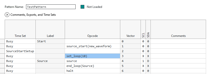 Note:
Note: To view the Source Waveform data at run-time, use an external digital scope.