For simplicity, the solutions described use the
set_loop Opcode in the Pattern file. This mitigates having to define multiple Vectors for each Waveform sample. Instead, the
set_loop Opcode will repeat the defined Vector for the specified amount of loop iterations. For a further explanation of this Opcode, refer to
Flow Control Opcodes.
There are two approaches that can be used to automatically ensure that the number of sourcing Vectors in a Pattern match the number of samples in a Source Waveform:
- Method 1: Use LabVIEW to write a value to a Digital Pattern Register, which will define the number of loop iterations to execute in the Pattern.
- Method 2: Use LabVIEW to programmatically modify a Pattern file to contain the correct number of Vectors/loops before recompiling it.
Method 1 is the recommended approach because it avoids decompiling and recompiling Pattern files. However, method 2 may be more suitable if large modifications to the Pattern file are necessary.
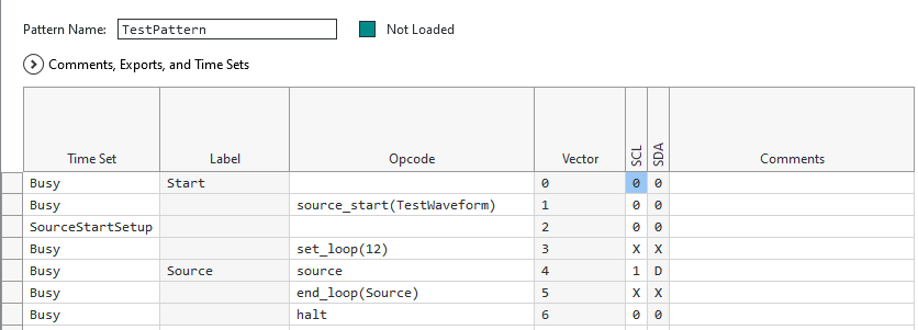
For demonstration purposes, this article references a Pattern file that contains the following Vectors:
Method 1: Writing to a Digital Pattern Register
Note: The full code and Digital Pattern Editor files used in this example can be found in the attached
Source Waveform- Write Register.zip file
1. In Digital Pattern Editor, open the Pattern file.
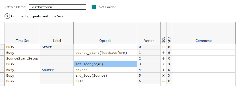
2. Modify the Vector containing the
set_loop Opcode to reference a Register.
- Set the Opcode to set_loop(regX) where X represents a number between 0-15.
- An example of this is shown below:
3. Initialize and load the NI-DIGITAL instrument and files.
- Refer to the example code located in C:\Program Files (x86)\National Instruments\LabVIEW 20xx\examples\instr\niDigital\Source Waveform for further guidance.
4. After loading the Pattern file with
niDigital Load Pattern VI, place a
niDigital Write Senquencer Register VI.
- Set the sequencer register input to the register specified in the set_loop Opcode of the Pattern file.
- Set the value input to the desired number of loop iterations.
5. Create and write the Source Waveform before bursting the Pattern.
Method 2: Modifying the Digital Pattern File
Note: The full code and Digital Pattern Editor files used in this example can be found in the attached
Source Waveform- Recompile Pattern.zip file.
1. In Digital Pattern Editor, export a
.digipatsrc file. This is the raw ASCII version of the
.digipat file.
- Navigate to File >> Export Pattern.
- Note the name of the file and where it's saved.
2. In LabVIEW, create a
.digitpatsrc file.
- Place a Open/Create/Replace File function onto the Block Diagram.
- Set the file path (use dialog) input to the location where the .digipatsrc file will be saved.
- This should be the same location that the exported Pattern file was saved to.
- Then set the operation (0:open) input to replace or create.
3. Write the raw ASCII Pattern file data to the newly created file.
- Connect a Write to Text File function to the Open/Create/Replace File function.
- Place a Concatenate Strings function on the Block Diagram and connect it's output to the text input of the Write to Text File function.
- Expand the Concatenate Strings function to display three inputs.
- On the first input of Concatenate Strings, connect a String Constant containing the text from the exported .digipatsrc file.
- Copy the text from the .digitpatsrc file and paste it into the String Constant.
- Delete all text after the "set_loop(" string.
- Below is an example of what the String Constant should contain:
//
file_format_version 1.1;
timeset Busy, SourceStartSetup;
pattern TestPattern (SCL, SDA)
{
Start:
Busy 0 0;
source_start(TestWaveform) Busy 0 0;
SourceStartSetup 0 0;
set_loop(
- On the second input of Concatenate Strings, connect a String Control that contains the number of loop iterations to execute.
- For example, if the Source Waveform contains 12 samples, set the String Control to contain the value "12".
- On the third input of Concatenate Strings, connect a String Constant that contains the remaining text from the .digipatsrc file.
- Below is an example of how this should appear:
) Busy X X;
Source:
source Busy 1 D;
end_loop(Source) Busy X X;
halt Busy 0 0;
}4. Close the newly created file.
- Connect a Close File function to the Write to Text File function.
- The code should now resemble the following image:
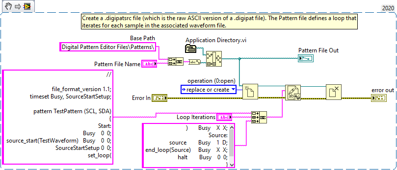 Note:
Note: This image is a LabVIEW snippet, which includes LabVIEW code that you can reuse in your project. To use a snippet, right-click the image, save it to your computer, and drag the file onto your LabVIEW diagram.
5. Compile the
.digipatsrc file into a standard
.digipat file.
- Place a System Exec VI on the Block Diagram.
- On the expected output size (4096) input, right-click and select Create Constant. Set the value to 9096.
- Using the same method, create a constant for the remaining inputs and ensure their values are as follows:
- wait until completion? (T) is True.
- standard input is an empty String Constant.
- working directory is C:\Program Files\National Instruments\Digital Pattern Compiler.
- run minimized? (F) is False.
- For the command line input, use a Concatenate Strings function to build the command.
- The first String must be set to cmd /c .\DigitalPatternCompiler.exe -pinmap "
- Follow this with the File Path to the Pin Map (.pinmap) file used in Digital Pattern Editor.
- Then, place a String Constant containing " " (quotation marks separated by a space).
- The next input should be the File Path to the .digipatsrc file that was created in steps 1-4.
- End the Concatenate Strings by connecting a final " character (closing quotation mark).
- Below is an example of how the completed VI should appear:
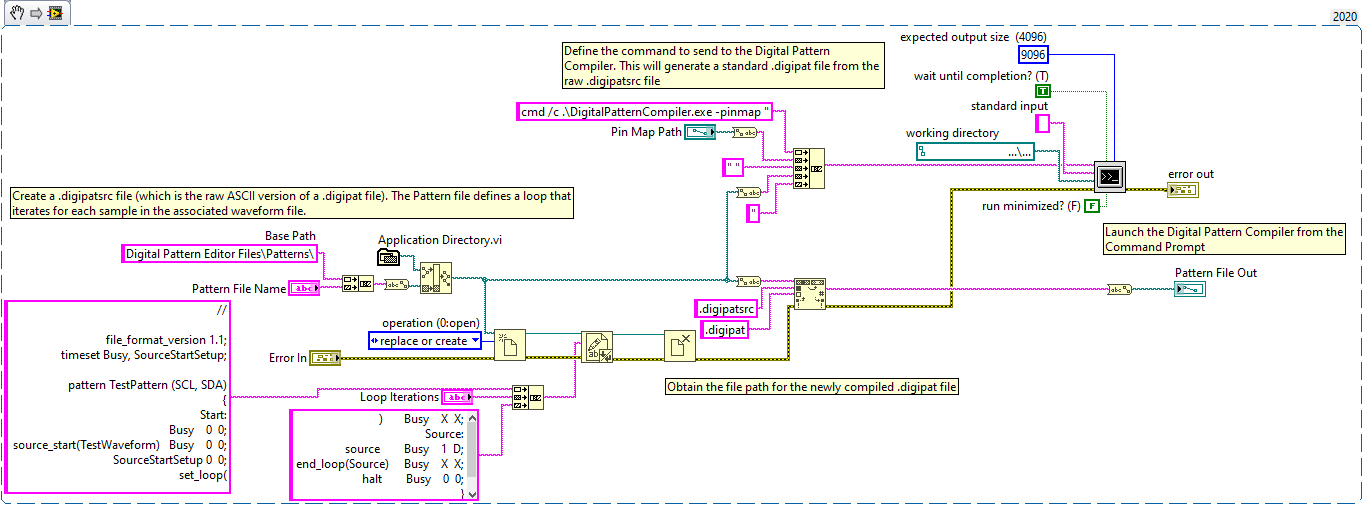 Note:
Note: This image is a LabVIEW snippet, which includes LabVIEW code that you can reuse in your project. To use a snippet, right-click the image, save it to your computer, and drag the file onto your LabVIEW diagram.
6. Obtain the number of samples in the Source Waveform.
- This depends on the method used to create the Source Waveform. If the Source Waveform is created from:
- A TDMS file - the number of samples can be obtained by reading the TDMS file.
- The niDigital Create Source Waveform VI - the number of samples can be obtained from the length of the Broadcast array input.