Configure NI Measurement & Automation Explorer (NI MAX)
1. Open NI MAX.
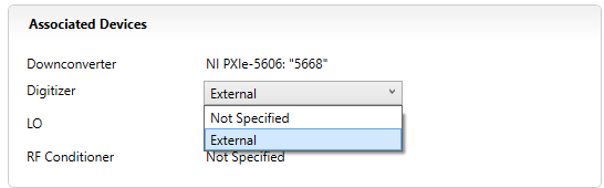
2. Select VSA (e.g. 5668) >> In Associated Devices section Specify Digitizer as “External”.
3. Select the correct Local Oscillator module from the drop-down menu against LO.
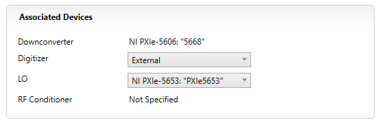
4. Click the “Save” button at the top.
LabVIEW Example
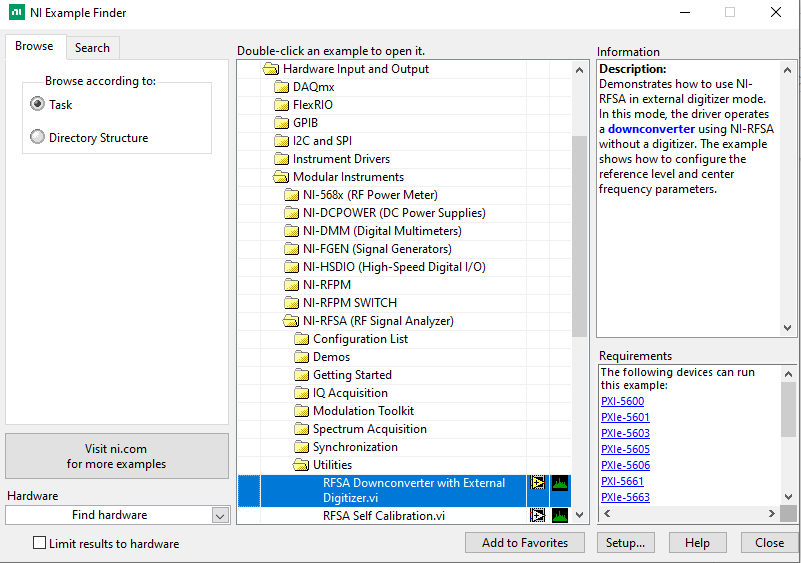
1. In LabVIEW, go to Help >> Find Examples.
2. In NI Example Finder browse to folder Hardware Input and Output >> Modular Instruments >> NI-RFSA >> Utilities.
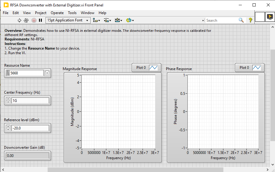
3. Open RFSA Downconverter with External Digitizer vi.
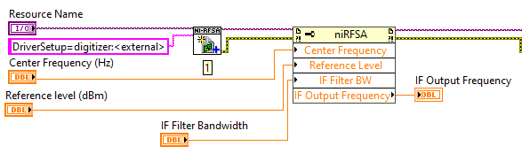
4. Configure the following Device Parameters; Resource Name, Center Frequency, and Reference Level in this example.
(Optional) Device-Specific Configuration
NI-RFSA drivers allow additional device-specific configuration apart from the one provided in example vi.
For example, PXIe-5668 can be configured for IF Output frequency of 190MHz, 199MHz, 187.5 MHz, 507.5 MHz, or 730 MHz. PXIe-5606 (downconverter in PXIe-5668) IF Output frequency can be configured by appropriately configuring the IF Filter BW property of NI-RFSA. PXIe-5606 Downconverter IF Filter can be set to 200 MHz/320 MHz, for IF of 730 MHz. As shown in the image below, the user can add a property node in the block diagram of the above example to specify IF Filter Bandwidth.