This content is not available in your preferred language.

The content is shown in another available language. Your browser may include features that can help translate the text.

Can I Connect the USB-621x D GND Pins to an External Ground?

Updated Apr 28, 2023

Reported In

Hardware

  • Multifunction I/O Device

Issue Details

  • I am using some Digital Input (DI) lines on a NI-USB 621x device. How should the ground pins be connected?
  • Can I connect a Digital Ground (D GND) pin on a NI USB-621x to an external ground reference?
  • What is the correct ground configuration for digital lines on a NI USB-621x device?
  • Where should I connect the ground of a Digital Output (DO) line on a USB-621x?

Solution

The DO and DI lines on a USB-621x are referenced to the D GND pins, which are all internally connected. For example, in the USB-6218 OEM pinout diagram below, pins 4, 6, 8, 10, 12, 14, 16 and 18 are all internally connected.
 
USB 6218 OEM pinout.png
Pinout for the USB-6218 OEM Device.
 

Connecting DO Lines

DO lines on any USB-621x device should only reference the D GND pins. Do not connect these to any external signal source, ground signal or power supply.

Connecting DI Lines

  • If using the USB-6210/6211:
    • The DI lines should reference the D GND pins.
  • If using the USB-6215/6218:
    • The DI lines should reference the D GND pins, which must be connected to the local ground of the system.
These connection requirements are illustrated in more detail below.
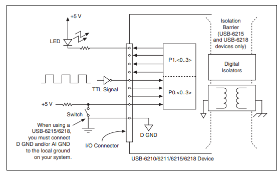
USB 6218 DI connection diagram.png
USB-6210/6211/6215/6218 Digital I/O Connections


Additional Information

A detailed breakdown of the connection requirements on a USB-621x can be found in the NI USB-621x User Manual.