The LO leakage can be improved by adjusting the IQ gains. In order to completely get rid of it, we can shift the LO out of the band leveraging the digital bandwidth of our transmitter or receiver. However, this results in the reduced usable bandwidth of the device.
Following are the steps needed to perform in order to push the LO leakage out-of-band.
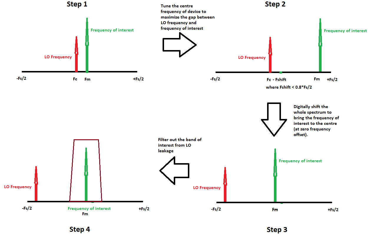
- Observe the signal of interest frequency and bandwidth in your spectrum.
- Tune your device center frequency such that the difference between the LO leakage frequency and frequency of interest increases. For example, if you would like to get a signal at 1.250GHz, tune your center frequency at 1.220GHz, i.e., 30MHz away from the actual signal (if your device’s real-time bandwidth allows this). This will give you enough room for filter roll-offs and also defines the LO leakage-free band that you can have. Please note that the maximum separation between the frequency of interest and the LO leakage is limited to half of the bandwidth of your device (typically 0.8 * Fs/2 where Fs is the sampling frequency).
- We generally need our message signal or frequency of interest at zero frequency offset. However, in the current case, our message signal is far off from the center. To bring it to the center, we need to apply a digital frequency shift that translates the whole digital spectrum.
- The last step is to get rid of LO leakage. This is generally done by decimation which automatically filters it out.
The following diagram shows these four steps:
(Fs: Sampling Frequency, Fc: Centre Frequency, Fm: Message Signal Frequency or Frequency of Interest, Fshift: Frequency by which spectrum will be shifted typically to create space between Fc and Fm)
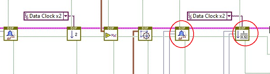
NI USRP RIO simple streaming projects already include the digital frequency shift and decimation IPs in its FPGA code chain as given below. Their values can be configured from the host. Please refer to the help files of these IPs for understanding the configuration options.
A similar concept can be applied to other NI RF devices such as NI Vector Signal Transceiver and NI Vector Signal Analysers. The digital shift can be applied using the
frequency offset property node.