Future wireless communication systems, such as 6G cellular communication systems, are expected to increasingly incorporate artificial intelligence and machine learning (AI/ML) principles. Researchers must train the underlying AI/ML algorithms to serve specific purposes in a wide variety of potential scenarios, which requires large datasets. The performance of AI/ML algorithms depends on the quality and representativeness of the datasets.
When testing and validating AI/ML models, researchers use different channel models and ray-tracing applications to generate datasets for specific scenarios and save datasets with different types and levels of metadata (scenario descriptions) in heterogeneous formats. This makes it difficult to generalize and compare AI/ML models and avoids a broader research community from adopting the datasets.
Augmenting AI/ML model training and validation with real-world RF datasets improves the robustness of the trained AI/ML algorithms in practical environments because real-world RF datasets include additional effects such as RF impairments and real-world channel properties that simulation environments do not cover.
AI/ML are defining technologies for future wireless networks. The NI RF Data Recording API generates real-world datasets that are critical in determining how AI/ML algorithms perform in the real world. The API provides comprehensive scenario descriptions in JSON-based SigMF metadata files. This simplifies the management of dataset libraries and allows more researchers to adopt the datasets.
To use the NI RF Data Recording API in Tx or Rx only operation mode, you need at least one NI RF USRP™ device. You must connect the devices to single or multiple host computers based on the API operation mode and the investigated application. The following figure shows the setup of a single Tx station and a single Rx station.
Complete the following steps to set up hardware for a system with or without mmWave devices
Non-mmWave Solution
- Install the network interface cards in the PCI-E slots of the PC.
- Connect the network interface cards to the USRP™ devices through QSFP28 to 4xSFP28 breakout cables.
- Determine which USRP™ device is the Tx station and which is the Rx station.
- Connect a 30 dB attenuator to the antenna port TX/RX 0 of Tx station's channel 0.
- Connect the 30 dB attenuator to the antenna port TX/RX 0 of Rx station's channel 0 through an SMA RF cable.
- Power on the PC and the USRP™ devices.
mmWave Solution
Complete the following steps to set up a system using mmWave devices (two beam formers and one dual-channel UDC) for a single Tx station and a single Rx station:
- Install the network interface cards in the PCI-E slots of the PC.
- Connect the network interface cards to the USRP™ devices through QSFP28 to 4xSFP28 breakout cables.
- Determine which USRP™ device is the Tx station and which is the Rx station.
- Connect the USRP™ devices, beam formers, and UDC into the same network using the switch and 1 Gig ethernet cables.
- Connect IF1 port of UDC with antenna port TX/RX 0 of Tx station via an SMA RF cable (sub6G).
- Connect RF1 port of UDC with the Tx beam former (ex. BBox One 5G) via an SMA RF cable (28-46G).
- Connect IF2 port of UDC with antenna port TX/RX 0 of Rx station via an SMA RF cable (sub6G).
- Connect RF2 port of UDC with the Rx beam former (ex. BBox Lite 5G) via an SMA RF cable (28-46G).
- Power on the PC, USRP™ devices, and mmWave devices.
Complete the following steps to set up a system using mmWave devices (two beam formers and two single-channel UDCs) for a single Tx station and a single Rx station:
- Install the network interface cards in the PCI-E slots of the PC.
- Connect the network interface cards to the USRP™ devices through QSFP28 to 4xSFP28 breakout cables.
- Determine which USRP™ device is the Tx station and which is the Rx station.
- Connect the USRP™ devices, beam formers, and UDCs into the same network using the switch and 1 Gig ethernet cables.
- Connect IF1 port of Tx UDC with antenna port TX/RX 0 of Tx station via an SMA RF cable (sub6G).
- Connect RF1 port of Tx UDC with the Tx beam former (ex. BBox One 5G) via an SMA RF cable (28-46G).
- Connect IF1 port of Rx UDC with antenna port TX/RX 0 of Rx station via an SMA RF cable (sub6G).
- Connect RF1 port of Rx UDC with the Rx beam former (ex. BBox Lite 5G) via an SMA RF cable (28-46G).
- Power on the PC, USRP™ devices, and mmWave devices.
ⓘ Ensure your host has enough free disk space and RAM.
ⓘ For mmWave solution, software and hardware setup for the beam former and the UDC depend on specific requirements and device operation guide the producer provides.
ⓘ Caution: Before using your hardware, read all product documentation to ensure compliance with safety, EMC, and environmental regulations.
ⓘ Caution: To ensure the specified EMC performance, operate the RF devices only with shielded cables and accessories.
ⓘ Caution: To ensure the specified EMC performance, the length of all I/O cables except for those connected to the GPS antenna input of the USRP™ device must be no longer than 3 m (10 ft.).
ⓘ Caution: The USRP™ RIO RF devices are not approved or licensed for transmission over the air using an antenna. Operating this product with an antenna may violate local laws. Ensure that you follow all local laws before operating this product with an antenna.
 | UHD | NI RF Data Recording API |
| Pandas, sympy, numpy, scipy, mako, yaml……. |  UHD python UHD python  | APIs |
| Install from pip | Clone from GitHub repo: UHD | Clone from GitHub repo: NI RF Data Recording API |
You can set up the software environment using either Docker or manual process.
Setting Up Software Environment Using Docker
ⓘ Docker is a set of platform as a service (PaaS) products that use OS-level virtualization to deliver software in packages called containers. Docker Engine hosts the containers. Docker, Inc provides both free and premium offerings.
With Docker, Windows and Mac users can run this application on a virtual Ubuntu 20.04 container instead of a natively installed Ubuntu. Docker automatically installs all the necessary software and drivers, helping Linux beginners to quickly get started.
Complete the following steps to set up the software environment:
Step 1: Install Docker by following the instructions on this page.
Step 2: Build and configure the environment with Docker by following the instructions: Install Dependencies and Run the API using Docker.
Setting Up Software Environment Using Manual Process
Complete the following steps to manually set up the software environment:
ⓘ Make sure you have the full control right of the Ubuntu 20.04.
After launching to Ubuntu 20.04 successfully, open the terminal and run the following commands:
# set Python environment path
sudo apt update
sudo apt-get install -y software-properties-common
echo "export PYTHONPATH=/usr/local/lib/python3.8/site-packages">>~/.bashrc
source ~/.bashrc

# install required packages
sudo apt install python3-pip
sudo python3 -m pip install pandas sympy scipy
sudo python3 -m pip install numpy==1.22


# install building tools and python dependencies for UHD
sudo apt install -y autoconf automake build-essential ccache cmake cpufrequtils doxygen ethtool fort77 g++ gir1.2-gtk-3.0 git gobject-introspection gpsd gpsd-clients inetutils-tools libasound2-dev libboost-all-dev libcomedi-dev libcppunit-dev libfftw3-bin libfftw3-dev libfftw3-doc libfontconfig1-dev libgmp-dev libgps-dev libgsl-dev liblog4cpp5-dev libncurses5 libncurses5-dev libpulse-dev libqt5opengl5-dev libqwt-qt5-dev libsdl1.2-dev libtool libudev-dev libusb-1.0-0 libusb-1.0-0-dev libusb-dev libxi-dev libxrender-dev libzmq3-dev libzmq5 ncurses-bin python3-cheetah python3-click python3-click-plugins python3-click-threading python3-dev python3-docutils python3-gi python3-gi-cairo python3-gps python3-lxml python3-mako python3-numpy python3-numpy-dbg python3-opengl python3-pyqt5 python3-requests python3-scipy python3-setuptools python3-six python3-sphinx python3-yaml python3-zmq python3-ruamel.yaml swig wget

# create a work directory and clone UHD repo
cd $HOME
mkdir workarea
cd workarea
git clone https://github.com/EttusResearch/uhd

# let's build UHD from source
cd uhd && git checkout v4.3.0.0 && cd host && mkdir build && cd build && cmake .. && make && make test && sudo make install

# setup the library references
sudo ldconfig
echo "LD_LIBRARY_PATH=/usr/local/lib">>~/.bashrc
source ~/.bashrc

# install net-tools which is needed to look at the ethernet card configuration and assign IP address to connected devices
sudo apt install -y net-tools dnsmasq

# install sigmf and pytest
pip3 install sigmf pytest

# install python package to read TDMS files
pip3 install npTDMS[hdf,pandas,thermocouple_scaling]

# install python colored output packages
pip3 install colored termcolor

# Install other packages
pip3 install matplotlib
pip3 install python-math

# Clone RF Data recording API from GitHub
cd $HOME/workarea
git clone https://github.com/genesys-neu/ni-rf-data-recording-api.git
After installing UHD, verify that UHD is ready to use USRP™ by running the uhd_find_devices command without any USRP™ device attached.
ⓘ The uhd_find_devices command is for finding UHD-supporting Software Radio Peripherals attached by USB, network, or embedded configuration. This command can use broadcast packets for discovery.
The following is an example output:
linux; GNU C++ version 4.8.4; Boost_105400; UHD_003.010.000.HEAD-0-g6e1ac3fc

No UHD Devices Found
The reason for "No devices found" is missing connection to a USRP™ device. If a USRP™ device is connected, its information, such as type and address, will be displayed.
Once you have built and installed the UHD, you need to import the UHD Python module. Python has an object called MultiUSRP which is an equivalent of the C++ multi_usrp API. The methods on both classes are the same and take the same arguments.
#On the terminal, run the following commands
python3
import uhd
After setting up and verifying the software environment, complete the following steps to configure the host PC's network interface:
Step 1: Identify the network interfaces by running the ifconfig command.
The following is an example output:
ens4f0: flags=4163<UP,BROADCAST,RUNNING,MULTICAST>  mtu 9000
…
ens4f1: flags=4163<UP,BROADCAST,RUNNING,MULTICAST>  mtu 9000
…
ens4f0 and ens4f1 are the interfaces that can be connected to USRP™ devices. The name and number of interfaces depends on the number of installed network ports.
(Optional) Step 2: Change the IP address of the interface by running the following command, for example:
sudo ifconfig ens4f0 192.168.10.1 netmask 255.255.255.0
sudo ifconfig ens4f1 192.168.11.1 netmask 255.255.255.0
sudo ifconfig ens4f2 192.168.12.1 netmask 255.255.255.0
sudo ifconfig ens4f3 192.168.13.1 netmask 255.255.255.0
Step 3: Access best performance of network by running the following commands, for example:
# To set the MTU size of all Eth ports connected to USRP™s to 9000 to get maximum sampling rate
sudo ifconfig ens4f0 mtu 9000 up
sudo ifconfig ens4f1 mtu 9000 up
# To set the default and maximum amount for the send/receive socket memory
sudo sysctl -w net.core.rmem_max=33554432
sudo sysctl -w net.core.wmem_max=33554432
sudo sysctl -w net.core.rmem_default=33554432
sudo sysctl -w net.core.wmem_default =33554432
# One can query the maximums and current settings with the following command:
ethtool -g ens4f0
# To change the number of TX/RX descriptors.
sudo ethtool -G ens4f0 tx 4096 rx 4096
sudo ethtool -G ens4f1 tx 4096 rx 4096
Step 4: Connect the USRP™ devices to the host PC.
You can connect the USRP™ X410 to the host machine using different options the Network Connectivity Guide for X410 provides.
Step 5: USRP™ Verify the connection between the USRP™ devices and the host PC by running the following command:
uhd_usrp_probe --args addr=192.168.10.2
If the command output displays errors regarding the FPGA version compatibility number, you must update the FPGA image before using your USRP™ device.
For more information, refer to the following link:
https://files.ettus.com/manual/page_usrp_x4xx.html#x4xx_updating_fpga
Clone the latest main branch of RF Data Recording API from GitHub by running the following command:
git clone https://github.com/genesys-neu/ni-rf-data-recording-api.git
For mmWave support, checkout the separate branch called main_mmwave-support under the folder of the repo you cloned:
git checkout main_mmwave-support
The following is the API architecture including the mmWave solutions:
# main
├─ build - # Contain all scripts related to build process
├─ docs - # API Documentation
│ ├─ Getting started guide to setup the system.pdf.
│ └─ figures
├─ resources - # For all static resources in the project. For example, images, i.e. spectrogram
├─ src/config - # Templates for all API Configurations and wireless link parameter map dictionary
├─ src/files - # Contains calibration table and AAKIT table of mmWave antenna array
├─ src/lib - # RF Data Recording API library
├─ src/tests - # Contains all tests (test API interfaces, plot spectrogram of Tx waveform, read SigMF metadata)
├─ src/tlk_core_log - # Contains log of executing api of mmWave devices
├─ src/waveforms - # Contains all waveforms for 5G NR, LTE, Radar and WiFi
│ ├─ main_rf_data_recording_api.py - # Main Script to execute the API in all RF modes, configured via configuration files.
│ ├─ rf_data_get_mmwave_devices_config_limitation.py - # Script to get value limits of mmwave antenna array parameters
│ ├─ rf_data_get_tmytek_api.py - # Script to clone the designated version of driver from GitHub and integrate it.
│ ├─ rf_replay_data_transmitter_usrp_uhd.py - # For Tx only, configured via terminal
│ ├─ rf_data_recorder_usrp_uhd.py - # For Rx only, configured via terminal
│ ├─ rf_data_pre_processing_plot.py - # Read SigMF metadata and plot time domain and spectrum of recorded IQ data
│ └─ rf_data_pre_processing_spectrogram.py - # Read SigMF metadata and plot spectrogram of recorded IQ data
├─ tools - # Contain scripts to automate tasks in the project
├─ README.md
└─ License.md - # MIT License
ⓘ For mmWave support, after you run the script rf_data_get_tmytek_api.py in the section Preparing for mmWave Support, the driver and related dependencies are copied and integrated to the current RF Data Recording API repository in your local machine.
After system setup, switch to <<repo>>/src folder and complete the following tasks to transmit and receive RF data.
Preparing for mmWave Support
If you use the mmWave solution, prepare the following driver and data before running the main script. Only TMYTEK-NI mmWave devices apply currently.
Driver API of mmWave DevicesCheck the script and edit the default value of input variables defined in this script and update if required.
Download and install the driver version compatible with the current API from the repo of the driver which is released by mmWave device producer, (for example:
GitHub) by running this command:
python3 rf_data_get_tmytek_api.py
This script helps you to clone the driver from GitHub and copy designated files to the current repository of NI RF Data Recording API in your local machine. After executing the above command, check if the
requirements.txt from the driver GitHub repo is copied into the
src/lib, which describes all dependencies of the driver. Then please install all listed python packages in this file using
pip.
You can also manually clone the driver and copy it to the right place within the current repository in your local machine.
AAKIT Table and Calibration Table
Put the AAKIT table file (.csv) and calibration table file (.csv) of the beam former to the /src/files folder as the src/files/README.md describes.
Note:
AAKIT table is the file describes the antenna information of the beam former, such as BBoxOne. Calibration table is the file describes the calibration information of the beam former, such as BBoxOne. All of them are in the USB disk along with mmWave devices.
For example:
Value Limits of Configurations for the Beam Former
Before editing the configuration file, get value limits of mmWave antenna array parameters by running the following command:
python3 rf_data_get_mmwave_devices_config_limitation.py
Running API in Tx-Rx Mode Based on Configuration File
Use the main_rf_data_recording_api.py in <<repo>>/src folder to run the API in Tx-Rx mode.
The API uses the configuration file config/config_rf_data_recording_api.json by default. You may need to change the path to store captured Rx data or if you want to use another configuration file, specify the configuration file name to the script by running the following command:
python3 main_rf_data_recording_api.py --config config/config_rf_data_recording_api.yaml
Learn about what a configuration file contains and how to modify a configuration file.
Here are templates for typical use cases:
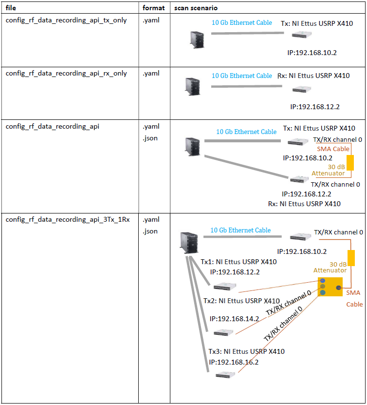
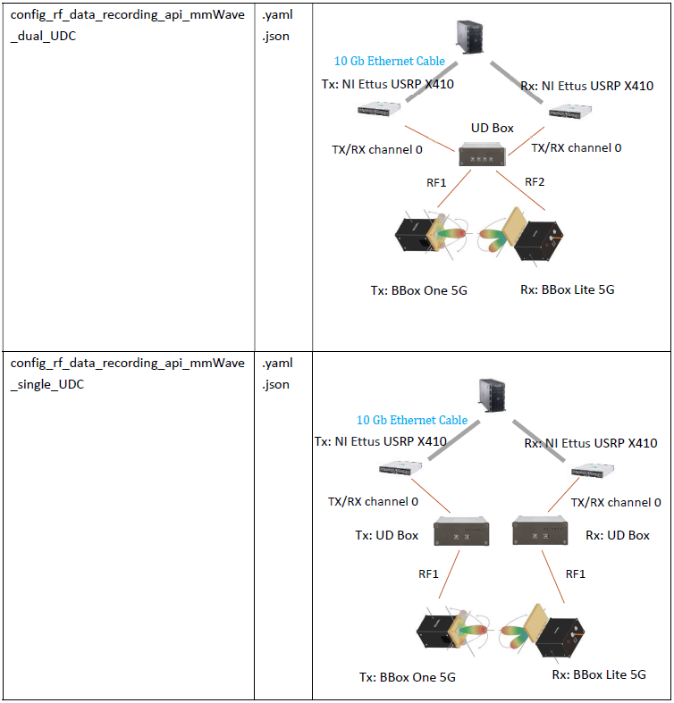
Detail of Configuration File
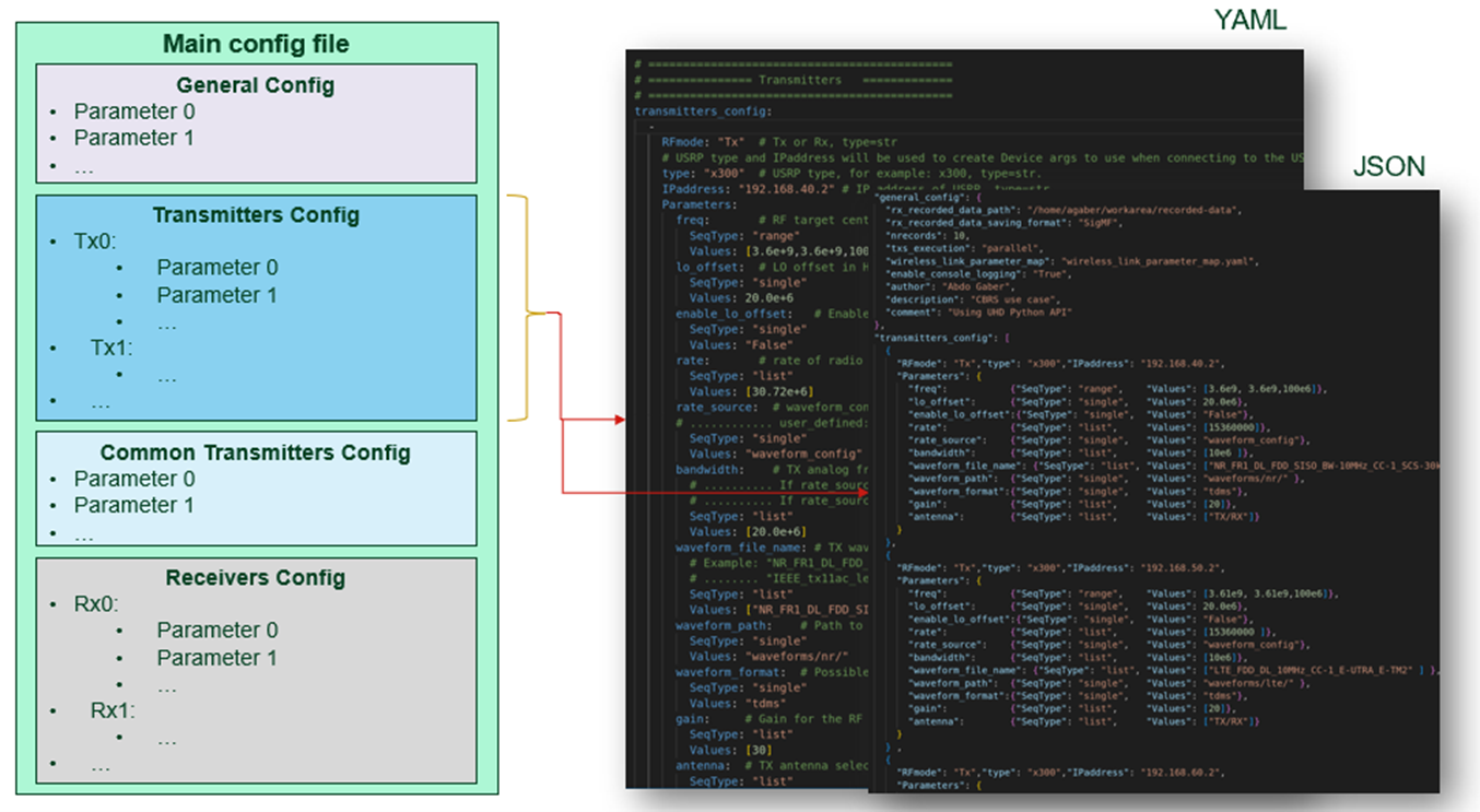
The following table describes the parameters in the configuration file config_rf_data_recording_api.yaml as an example:
General configuration: A list of basic parameters, such as the path of recorded data, the number of records, and description for the test case.
|
| rx_recorded_data_path | Path to store captured Rx data |
| rx_recorded_data_saving_format | Format in which Rx recorded data is saved. Possible value: SigMF |
| nrecords | Number of snapshots from RX IQ data acquisition |
| txs_execution | Tx USRP™s execution mode. Possible value: "parallel" or "sequential" |
| wireless_link_parameter_map | Parameter map dictionary that gives parameters pair |
| enable_console_logging | Enable or disable console logging |
Transmitters configuration: A list of parameters that you can sweep over for each transmitter, including RF configuration parameters such as the frequency, gain, sampling rate, and antenna port, and selected waveform-related parameters such as the waveform path, name, and format.
ⓘ You can configure the sampling rate and bandwidth or read values from the related waveform configuration file.
ⓘ SeqType means the parameter values in range (start, stop, step), list, or single.
If the API uses multiple transmitters, you can configure the API to run the TX stations in two modes by setting the txs_execution parameter to the following values:
- Parallel: Tx USRP™s transmit their related waveform simultaneously.
- Sequential: Tx USRP™s transmit their related waveform one by one in sequential manner: Transmit waveform1, record IQ data, Transmit waveform2, record IQ data, and so on.
Multiple Rx stations capture RF data in parallel.
|
| RFmode | Tx or Rx. This example uses Tx. |
| type | USRP™ type, for example, x4xx |
| IPaddress | IP address of USRP™ |
| freq | RF target center frequency in Hz |
| lo_offset | LO offset in Hz |
| enable_lo_offset | Enable LO offset, type: str2bool |
| rate | Rate of radio block |
| bandwidth | TX analog front-end filter bandwidth in Hz |
| rate_source | waveform_config or user_defined |
| waveform_file_name | TX waveform file name without extension |
| waveform_path | Path to TX waveform file or folder |
| waveform_path_type | relative or absolute |
| waveform_format | tdms, matlab_ieee, or matlab |
| gain | Gain for the RF chain |
| antenna | TX antenna selection (TX/RX) |
Common Tx Stations configuration: A list of parameters related to transmitters for clock reference configuration and waveform replay data configuration to have a continuous transmission.
ⓘ SeqType means the parameter values in range (start, stop, step), list, or single.
|
| tx_clock_reference | Tx sync reference source. Possible value: internal, external, or gpsdo. |
| tx_radio_id | Radio block to use. Possible value: 0 or 1. |
| tx_radio_chan | Radio channel to use |
| tx_replay_id | Replay block to use. Possible value: 0 or 1. |
| tx_replay_chan | Replay channel to us |
| tx_duc_chan | Duc channel to use |
| tx_duc_id | Duc id to use |
Receivers configuration: A list of parameters that you can sweep over for each receiver, including RF configuration parameters such as frequency, gain, sampling rate, antenna port, clock reference, and duration of record. You can configure the sampling rate or obtain this value from the Tx configuration. If there are multiple transmitters with different sampling rates, the maximum value isused.
ⓘ SeqType means the parameter values in range (start, stop, step), list, or single.
|
| RFmode | Tx or Rx. This example uses Rx. |
| type | USRP™ type, for example, x4xx |
| IPaddress | IP address of USRP™ |
| freq | RF target center frequency in Hz |
| lo_offset | LO offset in Hz |
| enable_lo_offset | Enable LO offset, type: str2bool |
| rate | Rate of radio block |
| bandwidth | RX analog front-end filter bandwidth in Hz |
| rate_source | waveform_config or user_defined |
| gain | Gain for the RF chain |
| antenna | RX antenna selection (TX/RX) |
| clock_reference | Rx sync reference source. Possible value: internal, external, or gpsdo. |
| duration | Rx time duration of IQ data acquisition |
| channel_attenuation | Expected channel attenuation in dB |
After modifying parameters in the configuration file, run the main script with this configuration file by executing the following command:
python3 main_rf_data_recording_api.py --config config/ config_rf_data_recording_api.yaml
ⓘ In Tx only or Rx only mode, you can use the above configuration file templates or pass the configurations directly from the terminal to use the RF Replay Data Transmitter and RF Rx Data Recorder scripts.
For mmWave solutions, you can reference comments of the related configuration files for the definition and usage of parameters.
Use the following scripts in Rx only mode for a single station:
- Main script based on a configuration file
- rf_data_recorder_usrp_uhd.py in the <<repo>>/src/ folder
Receive RF data from a single TX/RX channel by passing desired 1 channel number to the program
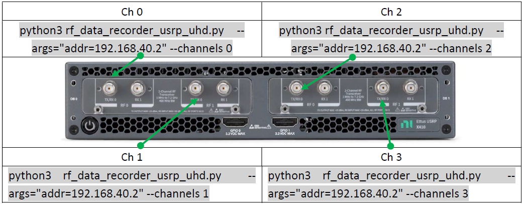
Run the following command to learn the arguments you need to consider when using the script rf_data_recorder_usrp_uhd.py:
python3 rf_data_recorder_usrp_uhd.py --help
The following is an example output of the previous command:
usage: rf_data_recorder_usrp_uhd.py [-h] [-a ARGS] [-o RX_RECORDED_DATA_PATH]
                                    [-f FREQ] [-r RATE] [-b BANDWIDTH]
                                    [-d DURATION] [-c CHANNELS [CHANNELS ...]]
                                    [-g GAIN] [-ant ANTENNA] [-ref REFERENCE]
                                    [-nr NRECORDS]
Obtain full control of RF parameters by passing all desired parameters to the program
Assume you want to record the IQ data and save the IQ data in SigMF to the /home/user/workarea/demo/recorded_data directory with the following parameter values: (frequency = 2 GHz, rate = 30.72 MS/s, channels = 0, gain = 30 dB, antenna = TX/RX0, duration = 10 ms, number of records = 1, USRP™ IP = 192.168.10.2). Run the following command:
python3 rf_data_recorder_usrp_uhd.py --nrecords 1 --args="type=x4xx,addr=192.168.40.2,master_clock_rate=245.76e6" --freq 2e9 --rate 30.72e6 --duration 10e-3 --channels 0 --gain 30 --bandwidth 400e6 --ant "TX/RX0" --rx_recorded_data_path recorded-data --reference "internal"
ⓘ After the recording process is complete, you need to manually update the metadata, such as signal_detail and signal_emitter, in the Rx Data Recorder script because Rx is running independently from Tx and the Rx Data Recorder script is not configured via the configuration file.
Receive RF data using the configuration file
Use the configuration file as the following template specifies:
src/config/config_rf_data_recording_api_rx_only.yaml.
After modifying parameters in the configuration file, run the main script with this configuration file by executing the following command:
python3 main_rf_data_recording_api.py --config
config/config_rf_data_recording_api_rx_only.yaml
In this way, you do not need to update the metadata manually.
Use the following scripts in Tx only mode for a single station:
- Main script based on a configuration file
- rf_replay_data_transmitter_usrp_uhd.py in the <<repo>>/src/ folder
Transmit RF data through a single TX/RX channel by passing desired 1 channel number to the program
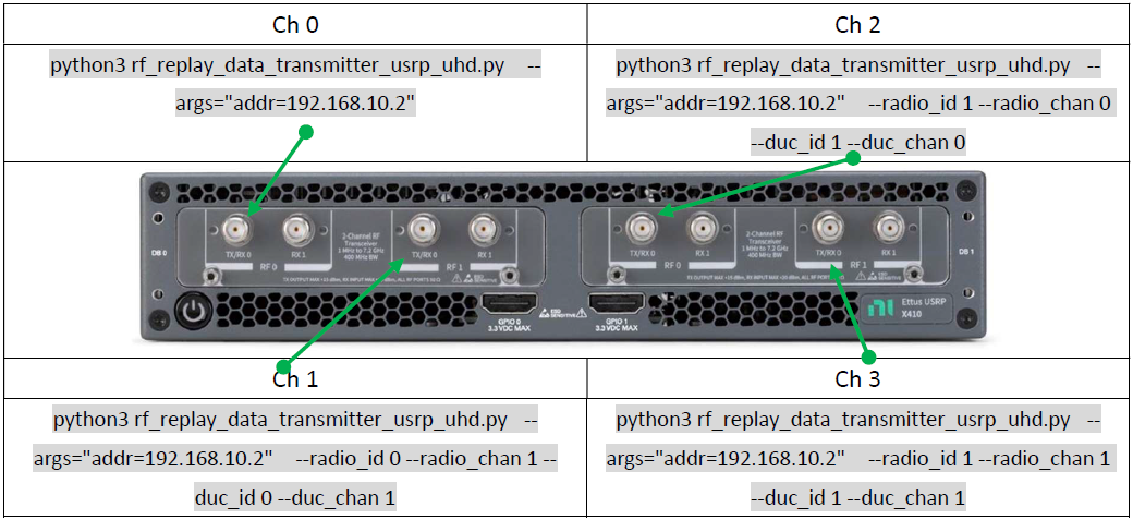
Run the following command to learn more information about the script rf_replay_data_transmitter_usrp_uhd.py:
python3 rf_replay_data_transmitter_usrp_uhd.py --help
Obtain full control of RF parameters by passing all desired parameters to the program
Assume you want to replay the 5G NR waveform NR_FR1_DL_FDD_SISO_BW-20MHz_CC-1_SCS-30kHz_Mod-64QAM_OFDM_TM3.1.tdms, with the following parameter values: (frequency = 2 GHz, rate = 30.72 MS/s, gain = 30 dB, antenna = TX/RX0, USRP™ IP = 192.168.10.2). Run the following command:
python3 rf_replay_data_transmitter_usrp_uhd.py --args="type=x4xx,addr=192.168.10.2,master_clock_rate=245.76e6" --freq=2e9 --rate=30.72e6 --radio_id=0 --radio_chan=0 --duc_id 0 --duc_chan 0 --gain=30 --bandwidth 400e6 --path="waveforms/nr/" --file="NR_FR1_DL_FDD_SISO_BW-20MHz_CC-1_SCS-30kHz_Mod-64QAM_OFDM_TM3.1" --waveform_format="tdms" --antenna="TX/RX0"
ⓘ To stop data transmission, click on the terminal ctrl+c.
Transmit RF data using the configuration file
Use the configuration file as the following template specifies: src/config/config_rf_data_recording_api_tx_only.yaml.
After modifying parameters in the configuration file, run the main script with this configuration file by executing the following command:
python3 main_rf_data_recording_api.py --config config/config_rf_data_recording_api_tx_only.yaml
ⓘ Tx does not create any recording file as Rx mode.
- This application supports data transmission and reception from multiple stations (USRP™s), where the number of RF channels per station (USRP™) is limited to a single RF channel when without the mmWave devices.
- This application is verified based on two beam formers and one dual-channel UDC) of TMYTEK-NI for a single Tx station and a single Rx station when with mmWave devices.
- This application doesn’t support simultaneously receiving and transmitting data with a single device.
- Due to the limitation from UHD Python API, the highest receive rate is 100M Samples/Second.
- The software mmWave driver version the example uses has restrictions on the calling path. For example, the relative path cannot be changed in this example. The driver developer may remove this restriction in future releases.