Solution
The Encoder is a device used for measuring and calculating the motor's speed and rotation. Usually, it has 3 outputs, A and B signals, for measuring the rotary speed and the direction of the motor), and a Z-Signal or Index Signal for calculating the number of rotations of the motor.
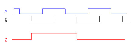
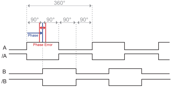
The phase difference between A and B signals is always 90° (there should be also counted the possible phase error of the device itself).
The signals themselves are digital signals, and the counter signal's characteristics are close to the digital signal's characteristics. The methods of measuring the phase are based on analog signal characteristics when there are real and imaginary components in the signal, but the digital and counter signals do not contain an imaginary component, so it is not possible to measure the phase shift with the NI-9361 Counter Input module.
As an alternative, you can use Analog Voltage Input Module and measure the phase shift with it. The measurement accuracy is dependent on the bitness of the device and the number of samples to measure during one iteration of the loop. You can use the attached VI as a base for calculating the phase shift of the encoder signals.