Section 1: Software Compatibility Issues:
- NI-RFSA driver installation is required for NI VSA and NI VST to detect and function properly. The minimum driver function required for any NI device based on the operating systems can be determined from this compatibility tool. The software installation can be verified from NI MAX>>My System>>Software.
- The order of installation is important. It is recommended to first install your development environment, such as LabVIEW, and then install the NI-RFSA driver. This will ensure that driver support is added to the development environment. If the sequence is not followed, you might not be able to find NI-RFSA driver APIs or examples in your development environment.
- The NI-RFSA driver automatically installs the RF Soft Front Panel (SFP) for easy interaction and taking quick first measurements. Incorrect installation or software corruption may cause SFP to throw an error during load. In such cases, repairing the drivers or a cycle of uninstall and reinstall is recommended. Please note that in newer versions of NI RF drivers, we have moved the SFP functionality to Instrument Studio.

Section 2: Hardware Detection and Configuration in NI MAX:If your hardware is not correctly detected in NI MAX and you have already verified the software installation as in section 1, then follow the below troubleshooting steps.
- Confirm the modules are inserted properly in the PXIe chassis. Make sure the slot you are using is compatible with the module. Refer to the device’s GSG for more information.
- Try changing the slot of the modules in your PXIe chassis.
- If you are using MXIe or Thunderbolt connectivity, please follow the relevant troubleshooting guide for MXIe or Thunderbolt.
- If the enumeration of modules in NI MAX does not show correctly, try resetting the NI MAX database. Please note that our multi-module RF devices need additional connections on the hardware level and manual configuration in NI MAX as explained in the device’s GSG (if applicable).
- Swapping the hardware with a similar unit can be helpful in identifying faulty devices. If a hardware fault is confirmed or further help in debugging is desired, please contact our Technical Support.
Section 3: PLL Lock or Clocking Issues:PLL lock failure or other clocking issues are commonly experienced problems in RF devices. There can be multiple reasons as discussed below:
- Make sure the clock source you are using is as per the tolerance of the RF device given in the specification sheet. Please note that several PXIe chassis clocks (especially non-timing&sync versions) cannot meet the tolerance required by the RF device.
- In case the clock is shared between multiple modules of the NI RF device, the reference clock sharing cable being damaged can result in these errors. A visual inspection of the cable or replacing it with a tested cable can be effective.
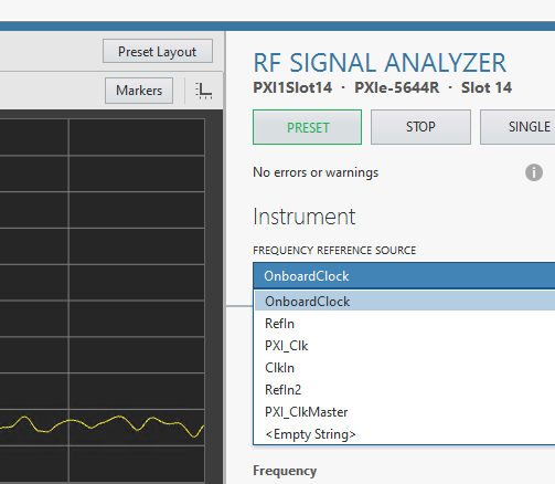
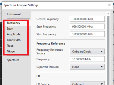
- The clock source (whether onboard, PXIe, or additional module) or sink (the RF module itself) may get faulty and lead to such errors. The best way to test is by swapping the clock source across onboard, PXI, or Ref In. If you have a timing module like PXIe-6674T, it can be used to derive the PXI backplane clock especially when the PXI chassis' own clock is not accurate enough. Similarly, if you have an external clock source, it can be applied to the Ref In connector of the device. NI RF Soft Front Panels allow swapping the clock sources interactively as shown below.

Clocking and PLL lock-related issues can be intermittent and dependent on temperature and mechanical aspects (such as shock or vibration, cable placement or position, etc.).
Section 4: Attenuated or Distorted or No RF Signal:If you are trying to observe an RF signal with NI VSA or VST but finding attenuated, distorted or no traces of signal, consider checking the following:
- For your first measurement or troubleshooting of such issues, we advise using our handy SFP.
- Consider checking the reference level, frequency, span, and sampling rate or resolution bandwidth (as applicable) settings on SFP.

- Distorted Signal: Reference level is the most common reason behind distorted or clipped signals. Please note that NI-RFSA drivers automatically adjust the gains or attenuators based on this setting. An inappropriate value of reference level may lead to clipping of the input signal and it may appear distorted. If the input signal is expected to be high power than the device limit, use an external attenuator to limit the signal power. If observing the signal in the time domain, make sure you are not facing aliasing. Please note that even if your sampling frequency is above Nyquist, the signal shape is not perfectly recovered unless you are sampling 5-10 times above the maximum frequency of the input signal.
- No RF Signal: If your signal is a short burst, there is a chance that NI-RFSA is not fetching during the burst time. Consider using IQ power triggers to capture your signal. These triggers are configurable using SFP. If your signal is very low in power, consider lowering the reference level to apply the appropriate amplification. Also, reduce resolution bandwidth to reduce the bin noise in the spectrum and thus lower the noise floor. Make sure that your RF device is sensitive enough to detect the input low-power signal.
- Attenuated Signal: Make sure to select the correct frequency setting and that you are not confusing the harmonic with the original signal.
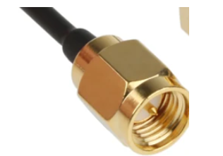
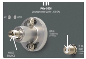
- Faulty RF, IF cable, or LO-sharing cables, are other common reasons for such issues. Generally, the cables are of male type while the connector on PXI/PXIe module is female. You can visually inspect the cable from the inside that the male pin is intact. Also, the joint of the cable with the connector is usually the most vulnerable point that should be inspected. Consider replacing the cables with known working ones if possible. Tighten up the RF cables with a torque wrench as recommended in the GSG.

- Validate your signal source with another signal or spectrum analyzer. Consider using the same RF cable (and any other intermediate circuitry like pre-amps, attenuators, etc.) as you are using with the other device under troubleshooting.
- Due to inappropriate handling, the connector on the PXI/PXIe RF modules can also get damaged. This can be easily identifiable with visual inspection in good lighting conditions.

- Calibration can be another reason for these kinds of issues. Running a self-calibration is highly recommended whenever there is any change in the hardware assembly, inter-module cables, location, or temperature since the last self-calibration was performed. Also, if the signal levels are inappropriate, self-calibration is recommended. Our devices also have a recommendation for external calibration intervals. This interval is available in the specification sheet or can be found here. Based on the operating conditions or faults, out-of-cycle calibration may also be needed.
- Hardware damage can be another possible reason. Depending on the device's use, any damage to the internal hardware component in the signal path can also lead to inappropriate measurements. For some hardware like PXIe-5831 or PXIe-5842, Self-Test can be initiated using NI MAX that validates the signal via an internal loopback between RF In and RF Out. If you have another similar VST or VSA, you can replace its modules or cables sequentially to identify the faulty component. Also, understanding the signal path of the hardware can accelerate the debugging and identification of the module that needs repair. In such cases, we recommend speaking with NI Technical Support.
Additional Information:RF measurement hardware is particularly sensitive and should be handled with some caveats. We recommend:
- Using only NI-provided cables for LO, Reference, ADC/DAC clock sharing, etc for the best performance.
- Using ESD sheets to place the hardware and ESD bands when physically handling the hardware like connecting cables, etc. Please see the getting started guide of your device for more details.
- For repairs and external calibration of NI RF devices, please send all the modules and cables even if they are not faulty to allow system-level calibration for better performance.