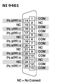
1. Check the specifications of your device to find the number of Input/Output buffers available. For example, the NI-9401 has two buffers (DIO 0 to 3 is a buffer and DIO 4 to 7 is another buffer).
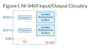
- If your device has more than 1 buffer (like the NI-9401), you can use one buffer to read the external clock and the other buffer for your Digital Output. Notice if you use one buffer to read the external clock (for example DIO0:3), you will be able to use only the channels of the other buffers as outputs (for example DIO4:7).
- You can also use a PFI input on your cDAQ chassis to connect your external sample clock.
- For both cases, make sure the specifications of your external clock match the PFI input capabilities of your Digital module or the cDAQ PFI input.
2. Modify the DAQmx Timing function to use your PFI as the Sample Clock Source of your Digital Output Task.
- If you are using LabVIEW you can use the Digital - Continuous Output.vi or Digital - Finite Output.vi examples. If you are using a text-based environment, you can use the equivalent examples: NI-DAQmx Example Locations for LabVIEW and Text-Based in Windows).
- Make sure you select the PFI terminal properly according to the line where you connected the external sample clock:
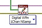
3. To output a pattern of bits, there are different ways. One of them is to create a waveform constant with the pre-defined sequence of bits and modify the DAQmx Write to Digital Waveform 1 Channel N Samples. In LabVIEW this will look like this: