For demonstration purposes, this article creates a digital pattern on a PXI-6534 with a sample rate of 25 μs. Modify the code accordingly to suit your device and desired sample rate.
1. Launch LabVIEW and create a new VI by clicking
File >> New VI.
2. From the
Measurement I/O >> NI DAQmx palette, place a
DAQmx Create Virtual Channel VI.
- Set the polymorphism to Digital Output.
- On the Lines input, create a Control. In the Control, specify a digital port that you wish to write to.
- For example, if using a PXI-6534 named "PXI1Slot2" in NI Measurement & Automation Explorer (MAX), the Control should be populated with PXI1Slot2/portX where X is a port number.
3. From the same palette, place a
DAQmx Timing VI.
- Connect Task Out from DAQmx Create Virtual Channel to Task In of DAQmx Timing.
- Connect Error Out from DAQmx Create Virtual Channel to Error In of DAQmx Timing.
- Create a Constant on the Samples Per Channel input. Set this value to the total number of samples that your pattern will consist of. Note: it's value must be a multiple of 4.
- Create a Constant on the Sample Mode input and set it to Finite Samples.
- Create a Constant on the Sample Rate input and set it to a rate supported by your device.
- For example, the PXI-6534 Specifications document states that a maximum sample rate of 20 MHz is possible.
- The inverse of the sample rate (1/sample rate) dictates the period of a single sample. For this example, a 40 kHz rate is chosen so that each sample is 25 μs.
- Create a Control on the Source input. Set it's value to a destination that has direct access to the device's timebase.
- Refer to What Internal Routes are Available on My Device? to check which destinations are suitable.
- Using the instructions in the linked article, we can see that for the PXI-6534, the /<PXI device>/Dig0/SampleClockTimebase destination has access to the /<PXI device>/20MHzTimebase source.
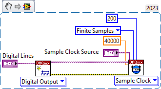 Note:
Note: This image is a LabVIEW snippet, which includes LabVIEW code that you can reuse in your project. To use a snippet, right-click the image, save it to your computer, and drag the file onto your LabVIEW diagram.
4. Place a
DAQmx Configure Output Buffer VI.
- Connect Task Out from DAQmx Timing to Task/Channels In of DAQmx Configure Output Buffer.
- Connect Error Out from DAQmx Timing to Error In of DAQmx Configure Output Buffer.
- Create a Constant on the Buffer Size (in samples per channel) input. Set it's value to a multiple of 4 that is larger than the Samples Per Channel input of DAQmx Timing.
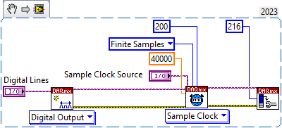 Note:
Note: This image is a LabVIEW snippet, which includes LabVIEW code that you can reuse in your project. To use a snippet, right-click the image, save it to your computer, and drag the file onto your LabVIEW diagram.
5. In parallel to the DAQmx VIs, place a
For Loop.
- Create a 2D array of unsigned byte integers and place it outside the For Loop. This array should have 1 row of 0s populated. This 2D array will hold all of the samples for your digital pattern where:
- Each column represents a line in the port (8 lines per port).
- Each row represents a sample for those lines.
- Connect the 2D array to the edge of the For Loop and replace it's tunnels with Shift Registers.
- Inside the For Loop, place an Insert Into Array function.
- Place an Increment function inside the For Loop and connect it's input to the Loop Iteration ("i" symbol).
- Connect the output of Increment to the Index 0 input of Insert Into Array.
- This ensures that each sample is appended to the end of the array.
- Connect the 2D array to the N-dim Array input of Insert Into Array.
- Outside of the For Loop, create a 1D array of unsigned byte integers. This array holds the next samples to be written into the pattern.
- Connect the 1D array to the New Element/Subarray input of Insert Into Array.
- Expand the 1D array to display 8 rows. Each row is 1 sample of each of the lines (this array is transposed in comparison to the 2D array). Populate each row with a value of 0 or 1 (low or high respectively).
- Create a Constant on the N terminal of the For Loop. Set it's value to the number of samples to be written for this specific pulse.
- For example, the snippet below shows a For Loop that iterates 100 times. Since a 40 kHz clock has been selected, each sample is 25 μs long. For 100 iterations, this pulse will be 2.5 ms long (100 x 25 μs = 2.5 ms).
- Connect the output of the Increment function to the right-edge of the For Loop. This wire will be used in subsequent For Loops.
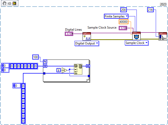 Note:
Note: This image is a LabVIEW snippet, which includes LabVIEW code that you can reuse in your project. To use a snippet, right-click the image, save it to your computer, and drag the file onto your LabVIEW diagram.
6. Place another
For Loop after the first
For Loop.
- Similar to before, create a Constant on the N terminal of the For Loop to define how many samples to write.
- The snippet below writes another 100 samples (i.e. a 2.5 ms pulse) of 1s.
- Place an Insert Into Array function.
- Connect the 2D array wire from before to the N-dim Array input of this Insert Into Array function. Note: remember to replace the array tunnels with Shift Registers.
- Connect an Increment function to the Loop Iteration ("i" symbol) terminal.
- Place an Add function.
- Connect the output of Increment to the X input of Add.
- Connect the output of Increment from the previous For Loop to the Y input of Add. This ensures that the next series of samples will still be appended to the end of the array.
- Create another 1D array of unsigned byte integers with 8 rows. Set each row to a value of 0 or 1, depending on your pattern requirements.
- Connect the 1D array to the New Element/Subarray input of Insert Into Array.
- The snippet below writes 100 samples of 1s on all 8 lines. Since the first For Loop wrote 100 samples of 0s, the combined output of both For Loops will appear as a square wave with a duty cycle of 50%.
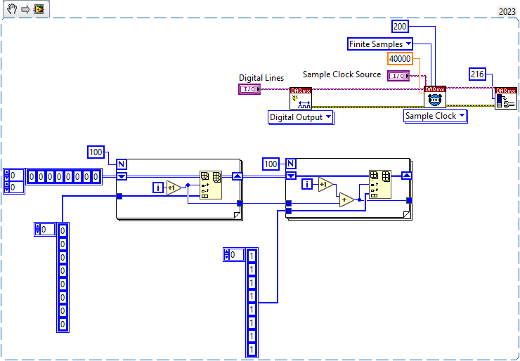 Note:
Note: This image is a LabVIEW snippet, which includes LabVIEW code that you can reuse in your project. To use a snippet, right-click the image, save it to your computer, and drag the file onto your LabVIEW diagram.
7. Repeat step 6 until you have completed the required pattern.
8. Once the pattern is complete, place a
Build Digital Data function.
- Connect the 2D array output from your last For Loop to the Data input of Build Digital Data.
- This function converts your pattern (2D array) to a digital waveform data type.
9. Place a
Build Digital Waveform function.
- Connect the output of Build Digital Data to the Y input of Build Digital Waveform.
- Set the value of dt to 1/sample rate. For example, if using a 40 kHz sample clock, dt should be set to 25E-6.
 Note:
Note: This image is a LabVIEW snippet, which includes LabVIEW code that you can reuse in your project. To use a snippet, right-click the image, save it to your computer, and drag the file onto your LabVIEW diagram.
10. Place a
DAQmx Write VI after
DAQmx Configure Output Buffer.
- Connect Task Out from DAQmx Configure Output Buffer to Task/Channels In of DAQmx Write.
- Connect Error Out from DAQmx Configure Output Buffer to Error In of DAQmx Write.
- Set it's polymorphism to Digital >> Single Channel >> Multiple Samples >> Waveform.
- Connect the output of Build Digital Waveform to the Data input of DAQmx Write.
- Create an Indicator on the output of Build Digital Waveform.
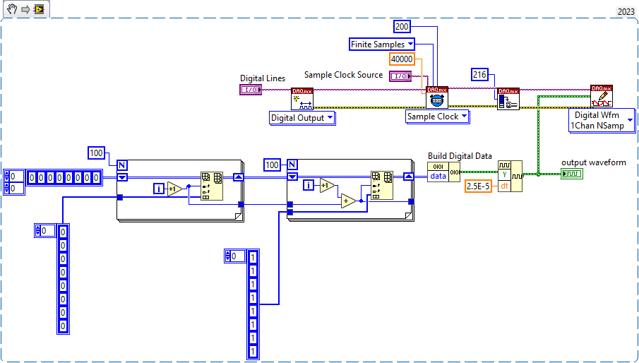 Note:
Note: This image is a LabVIEW snippet, which includes LabVIEW code that you can reuse in your project. To use a snippet, right-click the image, save it to your computer, and drag the file onto your LabVIEW diagram.
11. Place a
DAQmx Start Task VI.
- Connect Task Out from DAQmx Write to Task/Channels In of DAQmx Start Task.
- Connect Error Out from DAQmx Write to Error In of DAQmx Start Task.
12. Place a
DAQmx Wait Until Done VI.
- Connect Task Out from DAQmx Start Task to Task/Channels In of DAQmx Wait Until Done.
- Connect Error Out from DAQmx Start Task to Error In of DAQmx Wait Until Done.
13. Place a
DAQmx Stop Task VI.
- Connect Task Out from DAQmx Wait Until Done to Task/Channels In of DAQmx Stop Task.
- Connect Error Out from DAQmx Wait Until Done to Error In of DAQmx Stop Task.
14. Place a
DAQmx Clear Task VI.
- Connect Task Out from DAQmx Stop Task to Task In of DAQmx Clear Task.
- Connect Error Out from DAQmx Stop Task to Error In of DAQmx Clear Task.
- Create an Indicator on the Error Out of DAQmx Clear Task.
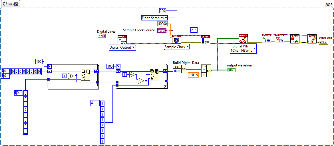 Note:
Note: This image is a LabVIEW snippet, which includes LabVIEW code that you can reuse in your project. To use a snippet, right-click the image, save it to your computer, and drag the file onto your LabVIEW diagram.
15. Run the VI and observe the digital pattern on the Front Panel.