To perform a loop-back test on your FlexRay interface device, follow these instructions:
1. Connect the 2 ports of your FlexRay device together by using an appropriate cable.
2. Create a blank VeriStand Project.
3. Set up the VeriStand project correctly to your target controller.
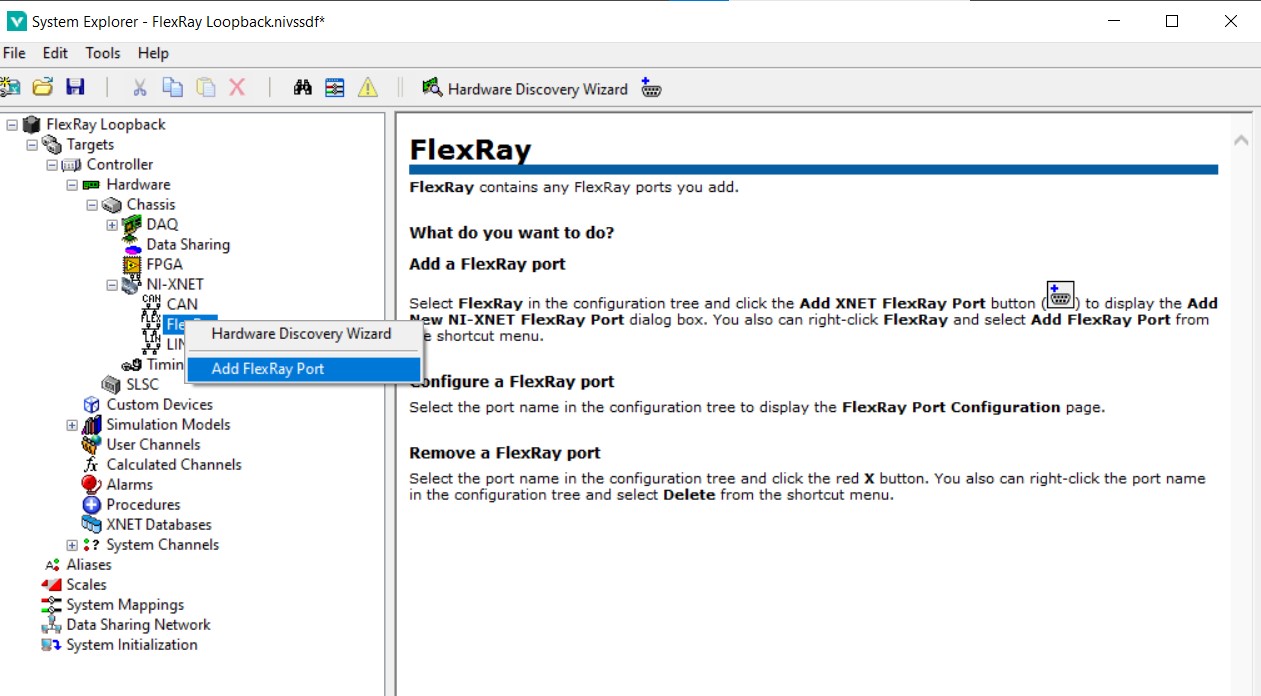
4. Add FlexRay port.
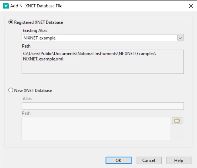
5. Add NI-XNET example database file.
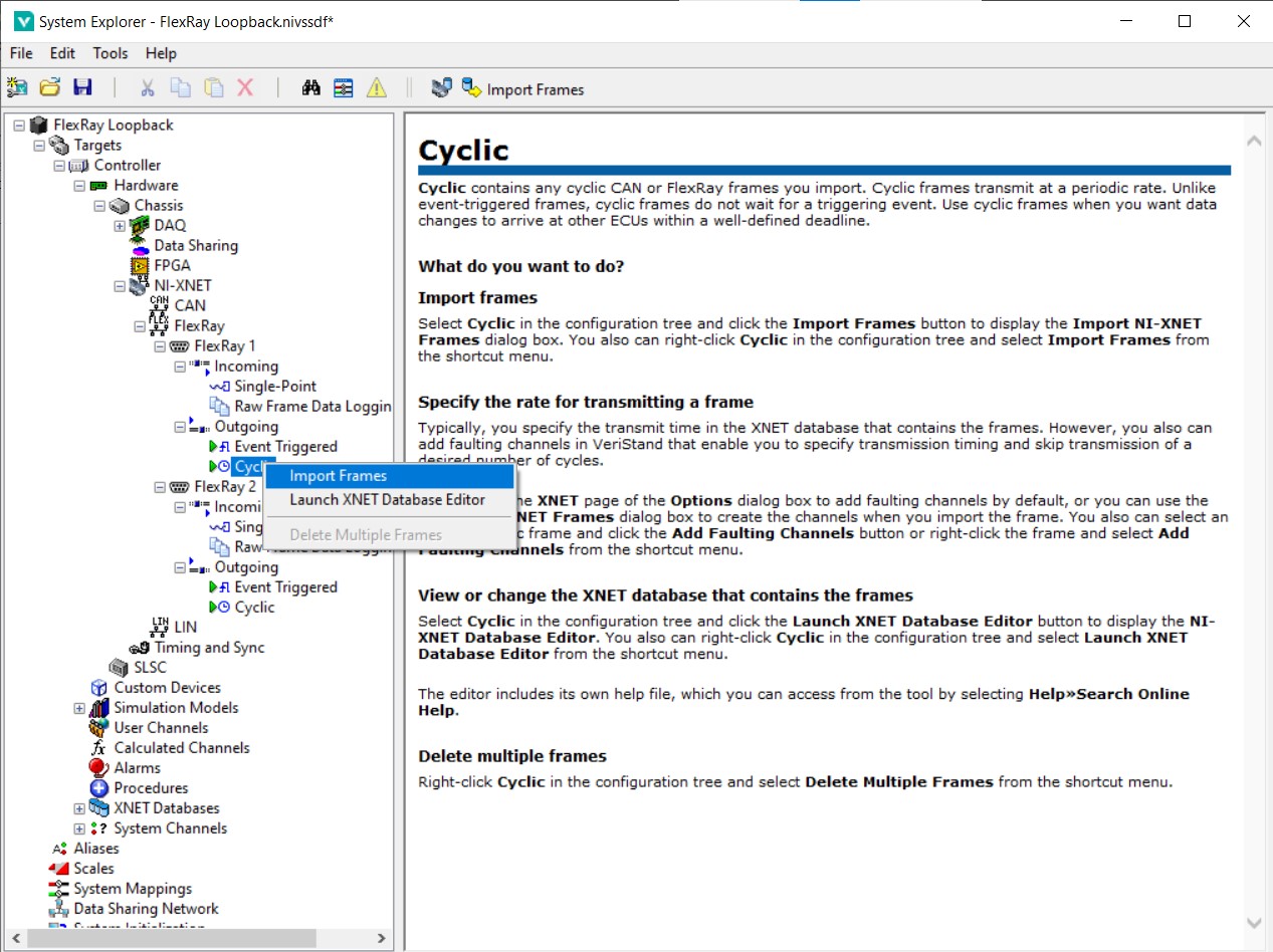
6. Click and open FlexRay Port 1 >> Outgoing. Right-click Cyclic and select import frames.
7. Select FlexRayCyclicFrame1.
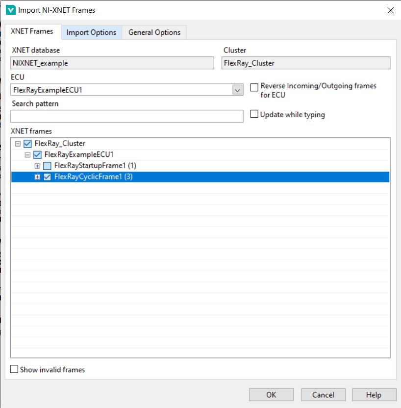
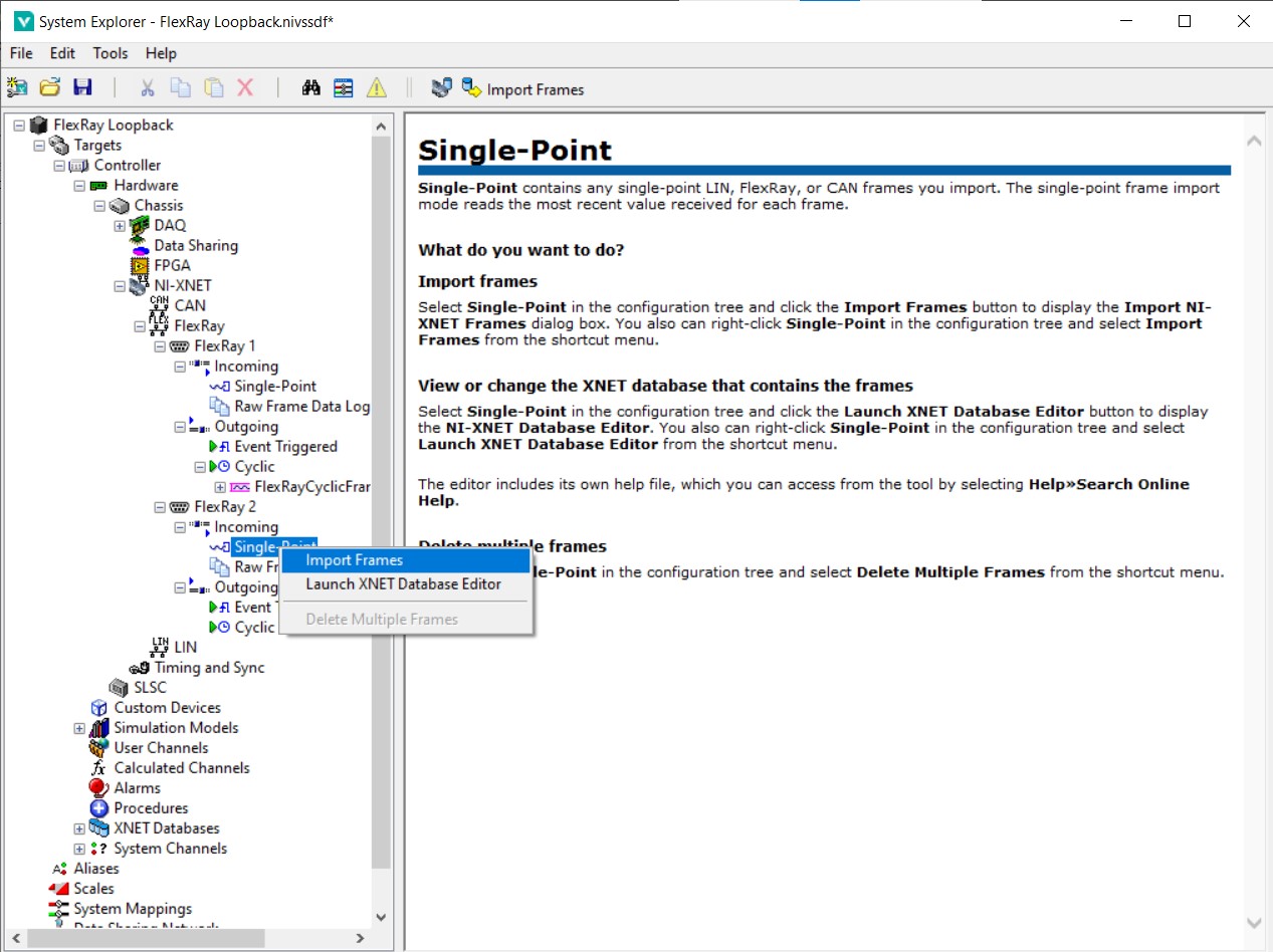
8. Click and open FlexRay Port 2 >> Incoming. Right-click Single-Point and select import frames.
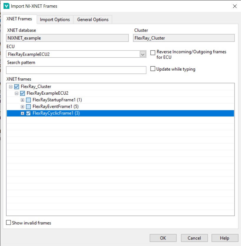
9. Change ECU to FlexRayExampleECU2 and select FlexRayCyclicFrame1.
10. Click FlexRay Port 1. Enable Cold Start if a start-up frame is not added in the
Outgoing and set Key Slot as a number that must be within the number of static slots in this cluster. If a start-up frame is added in the
Outgoing, it is not necessary to enable Cold Start.
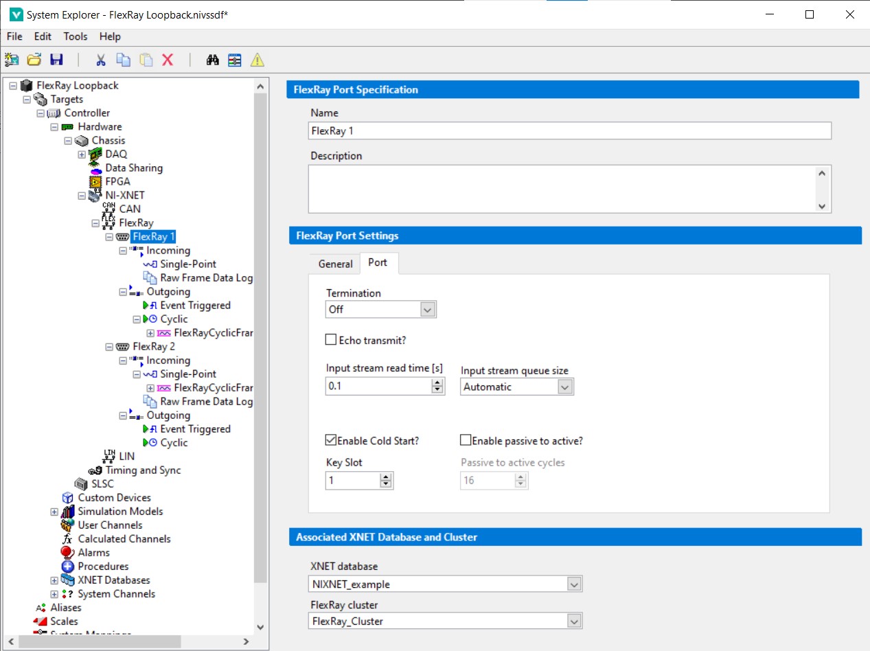
11. Click FlexRay Port 2. Enable Cold Start and set Key Slot as a number that must be within the number of static slots in this cluster.
12. Save and deploy the VeriStand project. You should be able to control FlexRay Port 2 reading value by changing the FlexRay Port 1 value.