Setting Analog Input Voltage Range
Previous generations of R Series multifunction reconfigurable I/O (RIO) devices had varying speeds for analog input—200 kS/s/ch for all NI 784xR devices and 750 kS/s/ch for all NI 785xR devices. USB R Series devices offer faster analog input rates over the previous generations—1 MS/s/ch for all NI USB-785xR devices. In addition to having matched analog input and output, USB R Series devices can also select the analog input voltage range. This gives you the ability to take higher resolution measurements at smaller voltage levels. You can select between ±10 V, ±5 V, ±2 V, and ±1 V.
Setting Analog Input Voltage Range via the Project Explorer
1. Right-click on FPGA Target and select Change I/O Configuration… to open the Configure R Series I/O dialog box.

Figure 1. Open the Configure R Series I/O dialog box.
2. In the Configure R Series I/O dialog box, select the Analog Input Channels that you would like to change the voltage range for. You can use the Shift and Ctrl keys to select multiple channels at once.
3. Select the voltage range you would like to use from the Voltage Range pull-down menu.
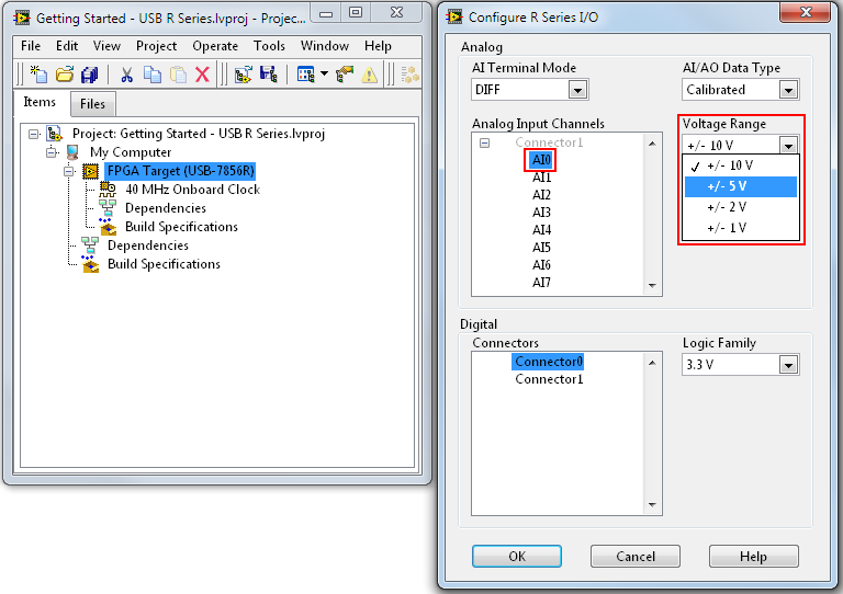
Figure 2. Select the analog input channel voltage range.
4. Click OK.
Setting Analog Input Voltage Range Programmatically
1. Make sure that you have added your I/O to the LabVIEW project. All analog I/O for USB R Series devices is on Connector1.
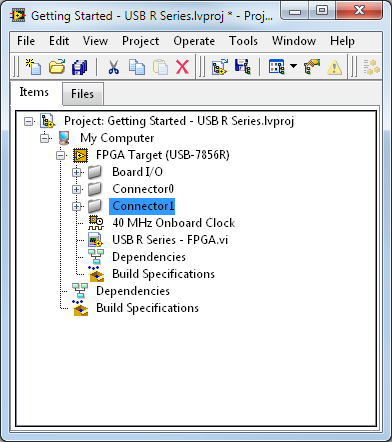
Figure 3. All analog I/O on USB R Series devices is on Connector1.
2. Add an FPGA I/O Property Node to your block diagram by right-clicking and selecting Programming»FPGA I/O»I/O Property.
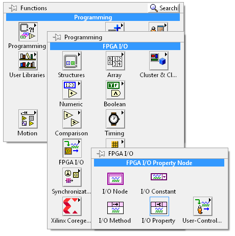
Figure 4. Add an FPGA I/O Property Node to your block diagram.
3. Right-click on the FPGA I/O Property Node and select Select Item»FPGA Target»Conector1, and then choose the channel for which you want to select the input range.
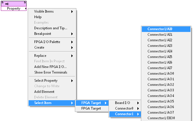
Figure 5. Select the channel for which you want to select the input range.
4. Left-click on the FPGA I/O Property Node and select Voltage Range.
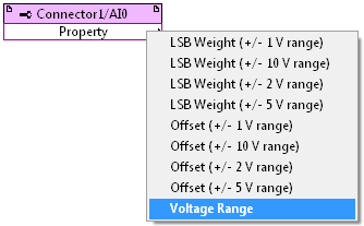
Figure 6. Select Voltage Range.
5. Right-click on the input terminal of the FPGA I/O Property Node and select Create»Control.
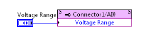
Figure 7. Final Voltage Range property selection.
Setting Analog Input Terminal Mode
Like previous generations of R Series devices, you can select the analog input terminal mode for USB R Series devices. You can select from differential (DIFF), referenced single ended (RSE), and nonreferenced single ended (NRSE). For USB R Series, the default AI terminal mode is differential (DIFF).
Setting Analog Input Terminal Mode via the Project Explorer
1. Right-click on FPGA Target and select Change I/O Configuration… to open the Configure R Series I/O dialog box.

Figure 8. Open the Configure R Series I/O dialog box.
2. Select the configuration you want from the AI Terminal Mode pull-down menu.
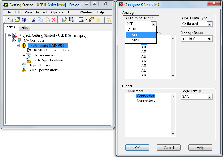
Figure 9. Select the analog input terminal mode.
Setting Analog Input Terminal Mode Programmatically
1. Make sure that you have added your I/O to the LabVIEW project. All analog I/O on USB R Series devices is on Connector1.

Figure 10. All analog I/O on USB R Series devices is on Connector1.
2. Add an FPGA I/O Property Node to your block diagram by right-clicking and selecting Programming»FPGA I/O»I/O Property.

Figure 11. Add an FPGA I/O Property Node to your block diagram.
3. Right-click on the FPGA I/O Property Node and select Select Item»FPGA Target.
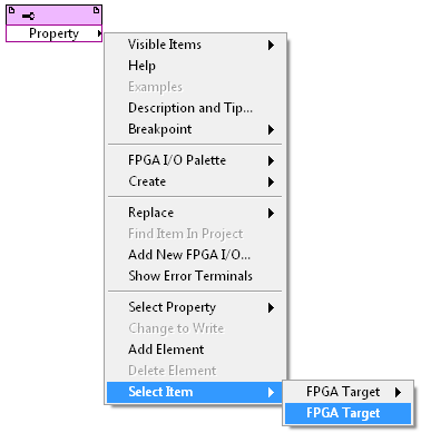
Figure 12. Select the FPGA Target.
4. Left-click on the FPGA I/O Property Node and select AI Terminal Mode.
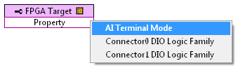
Figure 13. Select AI Terminal Mode.
5. Right-click on the input terminal of the FPGA I/O Property Node and select Create»Control.
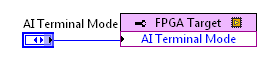
Figure 14. Final AI Terminal Mode property selection.
Note that the analog input terminal mode applies to all channels. You cannot select different terminal modes for different channels.
Setting Analog Input and Output Data Type
Previous generations of R Series multifunction RIO devices provided analog data using calibrated raw codes that use an I16 data type. Users would read or write the raw codes of the analog-to-digital converter or digital-to-analog converter respectively, and then convert them to engineering units on the host. USB R Series devices now provide an option to use uncalibrated raw codes (I16) or calibrated engineering units (FXP, ±27,5) directly out of the FPGA I/O Node.
To learn more about the differences between calibrated and uncalibrated data with USB R Series devices, and when you should choose between them, see Working With Calibrated and Uncalibrated Data on NI R Series Multifunction RIO Devices for USB. Unlike the other I/O settings described in this paper, the analog input and output data type can only be configured at compile time. Therefore, it can only be set using the Configure R Series I/O dialog box.
Setting Analog Input and Output Data Type via the Project Explorer
1. Right-click on FPGA Target and select Change I/O Configuration… to open the Configure R Series I/O dialog box.
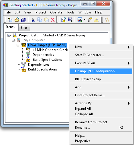
Figure 15. Open the Configure R Series I/O dialog box.
2. Select the configuration you want from the AI/AO Data Type pull-down menu.
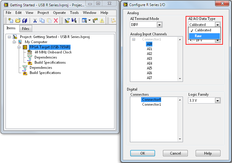
Figure 16. Select the analog input and output data type.
Note that the analog input and output data type applies to all channels. You cannot select different modes for different channels.
Setting Digital Input and Output Logic Levels
USB R Series multifunction RIO devices have 48 digital lines that you can configure as either input or output. Unlike previous generations of R Series devices that supported 3.3 V TTL, USB R Series devices support LVTTL with selectable logic levels. The available logic levels are 3.3 V, 2.5 V, 1.8 V, 1.5 V, and 1.2 V.
Setting Digital Input and Output Logic Levels via the Project Explorer
1. Right-click on FPGA Target and select Change I/O Configuration… to open the Configure R Series I/O dialog box.

Figure 17. Open the Configure R Series I/O dialog box.
2. In the Configure R Series I/O dialog box, select the Digital Connectors that you would like to change the logic levels for. Use the Shift and Ctrl keys to select multiple channels at once.
3. Select the logic level you would like to use from the Logic Family pull-down menu.
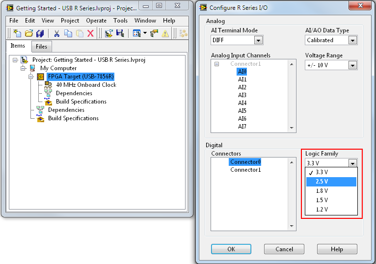
Figure 18. Select the digital I/O logic level.
4. Click OK.
Setting Digital Input and Output Logic Levels Programmatically
1. Make sure that you have added your I/O to the LabVIEW project. All high-speed digital I/O (up to 80 MHz) for USB R Series devices is on Connector0, and all standard-speed digital I/O (up to 10 MHz) for USB R Series devices is on Connector1.
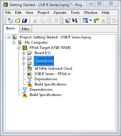
Figure 19. All digital I/O on USB R Series devices is on Connector0 and Connector1.
2. Add an FPGA I/O Property Node to your block diagram by right-clicking and selecting Programming»FPGA I/O»I/O Property.

Figure 20. Add an FPGA I/O Property Node to your block diagram.
3. Right-click on the FPGA I/O Property Node and select Select Item»FPGA Target.

Figure 21. Select the FPGA Target.
4. Left-click on the FPGA I/O Property Node and select Connector0 DIO Logic Family, or Connector1 DIO Logic Family, depending on what connector your I/O is on.
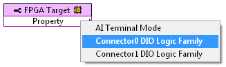
Figure 22. Select the DIO logic family.
5. Right-click on the input terminal of the FPGA I/O Property Node and select Create»Control.
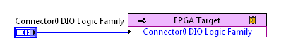
Figure 23. Final DIO Logic Family property selection.
Additional Considerations When Changing Digital Logic Levels Programmatically
A feature of USB R Series devices is that you can select the digital logic family programmatically. This means that while your program is running, you can change the logic level that your digital lines are using. For example, if your FPGA VI is running with the digital logic family set to 1.2 V and you change the logic family to 3.3 V, the voltage on your digital lines changes automatically. However, you should take special care when making this change within a single-cycle Timed Loop. When you change the digital logic family in a standard While Loop, the FPGA enable chain holds the output of the digital line until the voltage rail has had time to change. When using a single-cycle Timed Loop in the NI LabVIEW FPGA Module, the enable chain is removed so the hold does not occur. Therefore, if you change the digital logic family from 1.2 V to 3.3 V, you see a ramping in digital output while the voltage rail is changing. You can see this behavior in the figure below.
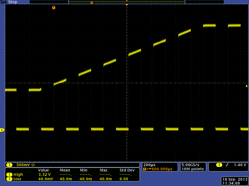
Figure 24. See the effect of changing the digital logic family in a single-cycle Timed Loop.
Using RIO Device Setup
USB R Series devices have onboard flash that you can use to store your FPGA bitfile. This is beneficial because it allows your FPGA VI to begin running as soon as your USB R Series device receives power. This can be beneficial for critical applications where you can’t wait for the operation system to boot, or if you want to operate your USB R Series device autonomously with no host processor. You use RIO Device Setup to deploy your bitfile to the USB R Series device, as well to determine when you want your application to begin running.
1. Right-click on FPGA Target and select RIO Device Setup… to open the Configure R Series I/O dialog box.
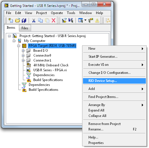
Figure 25. Open the RIO Device Setup dialog box.
2. To deploy a new bitfile, click on the Choose File button to select the bitfile you want to deploy.
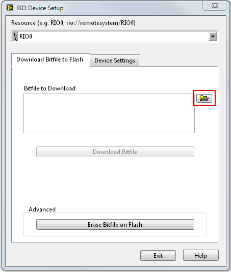
Figure 26. Choose the bitfile you want to deploy.
a. If there is already a bitfile downloaded on the USB R Series device, then you need to clear the bitfile by clicking on the Erase Bitfile on Flash button.
3. Click the Download Bitfile button.
4. Once the operation completes, click OK.
5. Select the Device Settings tab.
6. Choose the proper setting you wish to apply, and click the Apply Settings button.
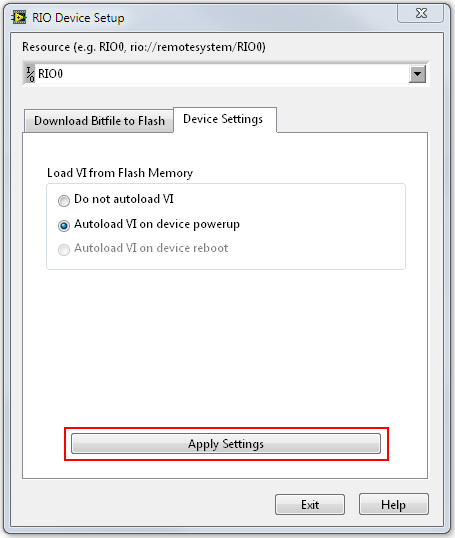
Figure 27. Click the Apply Settings button.
7. Once the operation completes, click OK.
8. If you are satisfied with all the settings you selected, click Exit.
Congratulations! You are now ready to begin developing your application using your USB R Series multifunction RIO device.