Creating the LabVIEW Project
Use LabVIEW projects to group together LabVIEW files and non-LabVIEW files, create build specifications for building a TPC VI into a TPC application, and eventually deploy the application to a Touch Panel device. You must use a project to build a TPC VI into a TPC application.
Complete the following steps to create a LabVIEW project, add a TPC target, and add a new TPC VI to the project.
-
Launch LabVIEW. In the Getting Started window, select Empty Project to open an empty LabVIEW project in the Project Explorer window as shown in Figure 1. LabVIEW creates an empty project with a Windows target, shown in Figure 1 as My Computer.
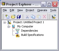
Figure 1. Project Explorer Window
-
Right-click the project, which is Project:Untitled Project 1 in Figure 1, in the Project Explorer window and select New » Targets and Devices from the shortcut menu to open the Add Targets and Devices dialog box as shown in Figure 2.
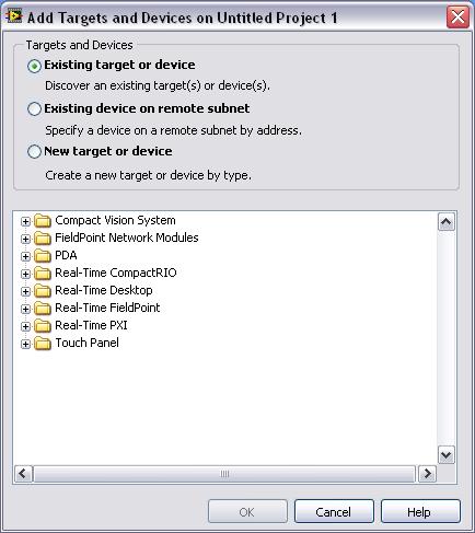
Figure 2. Add Targets and Devices Dialog Box
-
Expand the TPC folder and select Touch Panel Windows CE 4.2 Device as shown in Figure 3.
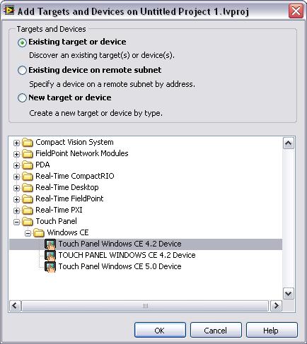
Figure 3. Adding a New Device
-
Click OK to add the target to the project. The target appears in the Project Explorer Window as shown in Figure 4.
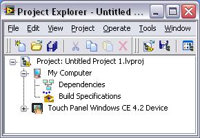
Figure 4. Adding the Touch Panel Windows CE 4.2 Device to the Project Explorer Window
-
Expand the TPC target as illustrated in Figure 5. Notice that LabVIEW automatically adds Dependencies and Build Specifications under the target. SubVIs appear under Dependencies when you add a VI that contains subVIs to a project. Build specifications that you create for a target in a project appear under Build Specifications in the Project Explorer window.
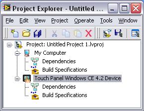
Figure 5. Expanding the TPC target in the Project Explorer
-
Right-click on Touch Panel Windows CE 4.2 Device and select New Touch Panel VI. This will bring up a template selection allowing you to pick between portrait and landscape screen layouts as shown in Figure 6. These templates are custom sized for TPC screens. Select 5.7” Touch Panel Landscape Screen and click OK.
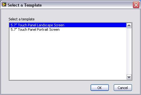
Figure 6. Selecting a layout for the TPC Template
-
This will open a TPC template with code already on the Block Diagram. Open the Block Diagram by selecting Window » Show Block Diagram. Notice that the there is a while loop and case structure already. This will allow the code that is placed in the True case of the case structure to run when the Run button is pressed on the Front Panel. The program will stop the while loop and exit when the Stop button is pressed.
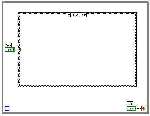
Figure 7. Template Block Diagram Code
-
Save the VI as TPC Tutorial.vi.
Creating the TPC VI
LabVIEW TPC Module essentially relies on the core functionality of LabVIEW. When a VI is targeted to a TPC, only the VIs that are available for that target are available on the palette.
Complete the following steps to construct a VI that will simulate a sine wave with a variable offset and frequency and display that sine wave on a graph.
Front Panel
-
Open the TPC Tutorial.vi that was saved previously. This should open to the Front Panel, but if not select Window » Show Front Panel.
-
Add a graph to the Front Panel. The graph can be found on the Controls » Modern » Graph » PDAWaveformGraph_2x. Notice that all TPC controls have been resized to allow them to be displayed property on a TPC screen.
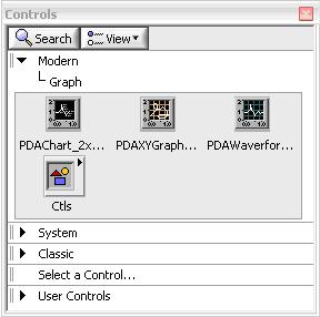
Figure 8. TPC Graph Palette
-
Place two sliders on the Front Panel, one horizontal and one vertical. Sliders can be found Controls » Modern » Numeric » HControl_2x and VControl_2x.
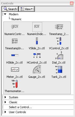
Figure 9. TPC Numeric Palette
-
To complete the Front Panel controls should be named and control settings need to be adjusted. Right-click on the Vertical Slide and select Properties. This will bring up the Property page for that control. Change the following properties to name the control Offset and allow you to adjust the offset of the sine wave from -2 to 2. Make sure to press OK when done configuring the properties.
Appearance » Label = Offset
Scale » Scale Range » Minimum = -2
Scale » Scale Range » Maximum = 2
-
Right-click the Horizontal Slide control and select Properties. Change the following properties to name the control Frequency and allow you to adjust the frequency of the sine wave by a factor of 0 to 6:
Appearance » Label = Frequency
Scale » Scale Range » Minimum = 0
Scale » Scale Range » Maximum = 6
-
Right-click the Wavefrom Graph indicator and select Properties. To make the graph display the data properly, me must turn off Autoscaling (which automatically scales the axes) and set the y-axis min and max to -4 and 4. This can be done by selecting Scales from the tabs at the top and then clicking the drop-down menu and selecting the y-axis. Make the Property Page look like the following by unchecking the Autoscaling option and setting the min and max to -4 and 4.
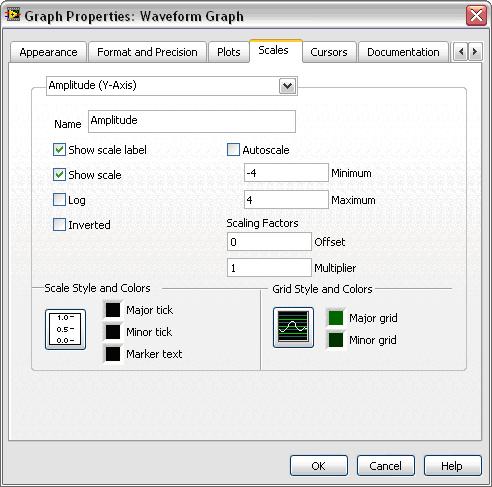
Figure 10. Waveform Graph Property Page
-
Rearrange the Front Panel to look similar to the Figure 11.
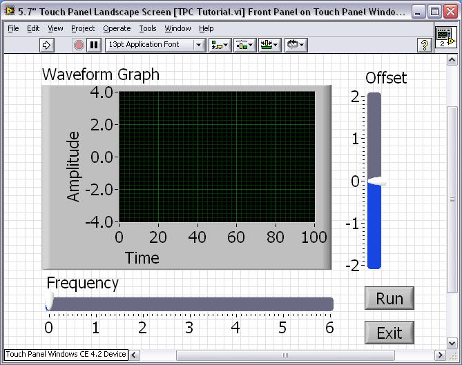
Figure 11. Complete TPC Tutorial Front Panel
-
Save the VI.
Block Diagram
-
Show the Block Diagram by selecting Windows » Show Block Diagram.
-
Place a Wait (ms) function inside the While loop but outside the case structure on the block diagram. When programming for TPC always remember to place wait functions in while loops to free the processor. This will make your TPC application run much better. The Wait functions are found on the Functions » Programming » Time, Dialog & Error. Right-click on the function and select Create » Constant and type 150. This will configure the Wait function to wait for 150 ms.
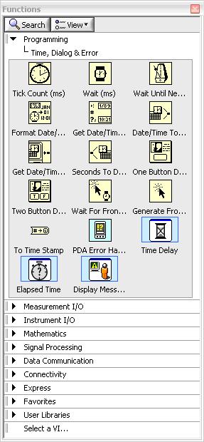
Figure 12. TPC Time, Dialog & Error Palette
-
To configure 100 points for the sine wave we will use a For Loop. This is found under the Functions » Programming » Structures palette. Place the For Loop on the Block Diagram inside the True case of the case structure. On the loop count terminal (N), right-click and select Create » Constant and type 100.
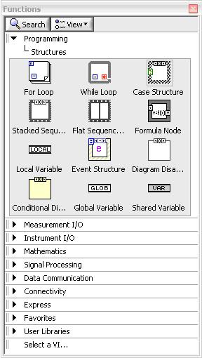
Figure 13. TPC Structures Palette
-
The remainder of the code is to calculate the points of the sine wave. The iteration count of the For Loop is used as the independent variable. This is scaled by the Frequency control, which is then an input to the Sine function. The output of the Sine function is then added to the Offset control. Complete the remainder of the Block Diagram to look like the following.
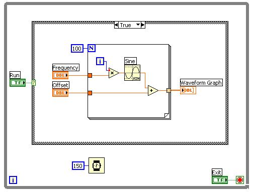
Figure 14. Completed Tutorial Block Diagram Code
-
Save the VI
Creating the TPC Build Specification
Build specifications contain the build settings and code generation options to use when you build a TPC VI into a TPC application. You can create the build specification when you create a project or wait until you are ready to build the TPC VI into a TPC application.
You can have multiple build specifications for the same target. For example, you might want one build specification that generates debugging information and another build specification that does not generate this extra information.
Complete the following steps to create a build specification.
-
Right-click Build Specifications under the TPC target and select New » Application (EXE) from the shortcut menu.
-
LabVIEW prompts you to save the project. Click the Save button when prompted and save the project as TPC Tutorial.
-
Click the Help button to open the LabVIEW Help and read a description of each build setting.
-
Enter TPC Tutorial in the Build specification name text box as shown in Figure 15.
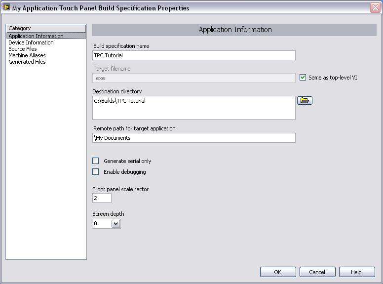
Figure 15. Creating the Build Specification
-
Select Source Files from the Category list and select TPC Tutorial.vi in the source files list. Click the blue right arrow button to move the VI from the source files list to the Top-level VI text box as shown in Figure 16.
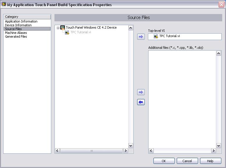
Figure 16. Selecting the Top-Level VI for the Application
Note: The Machine Alias category is not used in this tutorial. You use the Machine Alias category to overwrite the default IP address of a shared variable host target so you can move the shared variable to a different host without rebuilding the application. Refer to the Using Shared Variables in PDA and Touch Panel VIs topic in the LabVIEW Help for more information about using shared variables.
-
Select the Generated Files category to view the filenames and path to the files the TPC Module will generate when you build the TPC Tutorial VI into a TPC application.
-
Click the OK button. The build specification you just created appears in the Project Explorer window under the TPC target as shown in Figure 17.
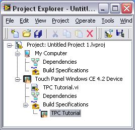
Figure 17. TPC Build Specification in the Project Explorer Window
-
Select File » Save Project in the Project Explorer window to save the project. Build specifications are saved with the project.
Building the TPC VI into a TPC Application and Deploying
After you develop the TPC VI on the host computer, you build the TPC VI into an executable TPC application that you can run on a TPC target. Pick one of the options in the Using the Shortcut Menu section or the Using the Run Button section to build, run, and deploy a TPC application.
Using the Shortcut Menu
Right-click the build specification and select one of the following from the shortcut menu:
- Deploy — Builds the TPC VI into a TPC application, if necessary, and deploys the application to the TPC target. This option does not automatically run the TPC application.
- Run — Builds the TPC VI into a TPC application, if necessary; deploys the application to the TPC target, if necessary; and automatically runs the TPC application.
- Build — Builds the TPC VI into a TPC application. This option does not deploy or automatically run the TPC application.
NOTE: For the TPC-2012, since it’s connected to you computer network via an Ethernet cable, you would not be able to directly deploy or run your applications through the LabVIEW Project Explorer. You would need to locally build your application and then transfer it over to the TPC-2012 using FTP.
Using the Run Button
The behavior of the Run button differs from LabVIEW for Windows:
- If you want to build, run, and deploy—Click the Run button in a TPC VI to build the TPC VI into a TPC application, deploy the TPC application to the TPC target, and run the TPC application on the TPC target. LabVIEW prompts you to create a build specification if you do not have an existing build specification for the TPC VI. If you have multiple build specifications, the TPC Module uses the default build specification, which the TPC Module indicates with a green square around the TPC build specification glyph in the Project Explorer window.
- If you want to build without deploying or running—Press the <Ctrl> key while you click the Run button in a TPC VI to build the TPC VI into a TPC application without deploying or running the TPC application. LabVIEW prompts you to create a build specification if you do not have an existing build specification for the TPC VI. If you have multiple build specifications, the TPC Module uses the default build specification, which the TPC Module indicates with a green square around the TPC build specification glyph in the Project Explorer window.
Closing the TPC Application
Click the Exit button in the TPC application on the TPC target to close the TPC application.
Debugging the TPC Application
You must create a build specification that enables debugging before you can debug a TPC application. Enabling debugging generates extra debugging information and can significantly increase the size of the TPC application.
When LabVIEW on the host computer connects to the TPC target, the TPC application runs on the TPC target. The front panel is fully functional on the TPC target. However, the front panel controls have no effect on the TPC application, and the indicators of the TPC VI on the host computer do not reflect the execution of the TPC application on the TPC target.
The block diagram acts as a conduit between the TPC application running on the TPC target and the TPC VI running on the host computer, where you can probe signals, set breakpoints, and step through code as you do in any other VI.
Tip: You can modify an existing build specification by double-clicking the build specification in the Project Explorer window or right-clicking the build specification and selecting Properties from the shortcut menu. This tutorial creates a second build specification for debugging.
Creating a Debugging Build Specification
Complete the following steps to create a debugging build specification.
-
Right-click Build Specifications under the TPC target and select New » Application (EXE) from the shortcut menu.
-
Enter (Debug) TPC Tutorial in the Build specification name text box.
-
Remove the checkmark from the Same as top-level VI checkbox so you can change the TPC application name.
-
Enter (Debug) TPC Tutorial.exe in the Target filename text box.
-
Place a checkmark in the Enable debugging checkbox to generate debugging information when you build the TPC VI into a TPC application as shown in Figure 18.
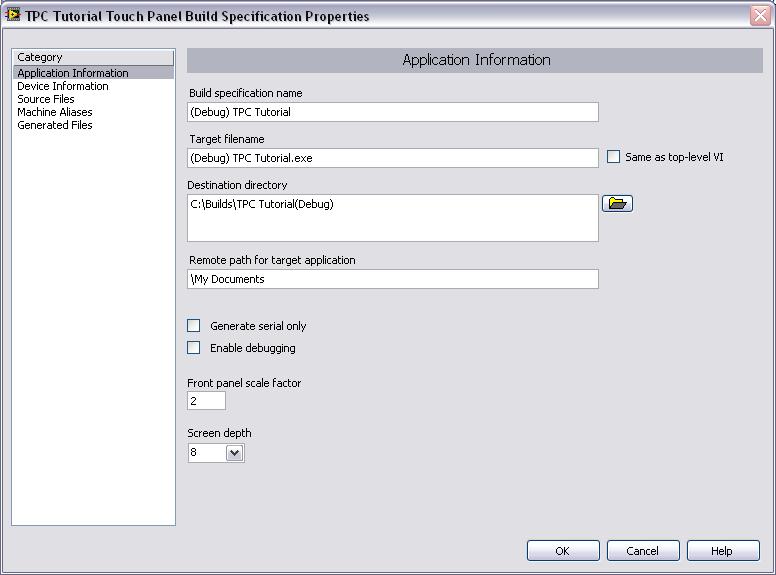
Figure 18. Creating the Debugging Build Specification
-
Select Source Files from the Category list and select TPC Tutorial.vi in the source files list. Click the blue right arrow button to move the VI from the source files list to the Top-level VI text box.
-
Click the OK button. The build specification you just created appears in the Project Explorer window as shown in Figure 19.
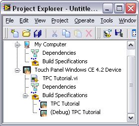
Figure 19. Two Build Specification in the Project Explorer Window
Adding a Probe to the TPC VI
Probes display information about the data that passes through a wire. As you interact with the TPC application on the TPC device, you can see the data passing through the wire in the TPC VI on the host computer.
Complete the following steps to add a probe to the TPC VI.
- Select Window » Show Block Diagram in the VI to open the Block Diagram if it is not visible.
Note: Double-click the VI in the Project Explorer window to open the VI if the VI is not already open. The Block Diagram acts as a conduit between the TPC application running on the TPC target and the TPC VI running on the host computer.
-
Right-click the wire that is flowing from the Frequency control to the for loop and select Probe from the shortcut menu.
A floating Probe window appears after you create a probe. LabVIEW numbers the Probe windows automatically and displays the same number in a glyph on the wire you probe as shown in Figure 20.
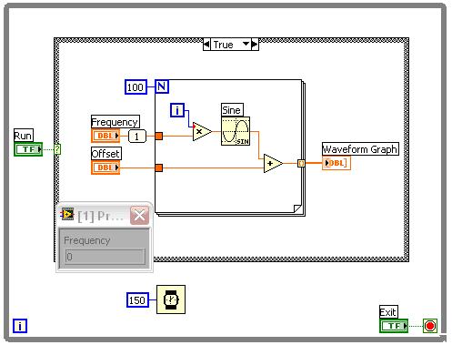
Figure 20. Adding the Probe to the Block Diagram
Deploying and Debugging a TPC Application
You must use the debug build specification to deploy the TPC VI, which contains debugging information, to the TPC device before the probe in the TPC VI on the host computer can update the values passing through the wire.
Complete the following steps to deploy and debug the TPC application.
-
Right-click the build specification for the TPC VI you want to build and deploy, which is (Debug) TPC Tutorial in Figure 19, and select Debug from the shortcut menu. Save any VIs if prompted.
The TPC Module builds the TPC VI into a TPC application, deploys the TPC application to the TPC target, and runs the TPC application on the TPC target as shown in Figure 21.
Tip: You also can start a debugging session by clicking the Step Over or Step Into buttons or by clicking the Pause button and then clicking the Run button on the block diagram toolbar.
-
Move the Frequency slider in the TPC application running on the TPC target and click the Run button. The value in the Probe window on the block diagram updates as you move the slider in the TPC application.
Note: Any changes you make on the front panel of the TPC VI on the host computer have no effect on the TPC application running on the TPC target.
-
Click the Exit button in the TPC application on the TPC target to stop the TPC application and end the debugging session.