The following are general requirements for implementing a 2-station Ethernet LAN-based RDA setup:
Note: If this step fails, check with your network administrator. The remote device may be behind a firewall, so you will need to ask the network administrator how to access it.
- Launch Measurement & Automation Explorer (MAX). Right-click on Devices and Interfaces and choose Create New, then RDA/Ethernet Device, then click Finish. Next, in the dialog box that appears, type the IP address of the server computer, choose the device you want, and finally select a device number that is not currently used in this computer. The remote device should now appear listed under Devices and Interfaces in MAX. If you chose to install an SCXI system in the server, this will not appear in the client PC Devices and Interfaces list when you connect to the RDA Server.
- Test the resources of this new device to ensure it is working properly. If it passes the test, then the RDA setup is correct. To perform this operation, right-click the new device icon under Devices and Interfaces, and in the Configuration window, click the Modify Configuration... button. Refer to the following figure for an illustration of this step.
Note: You can also modify the configuration of the remote DAQ device from the client computer in another way. Launch MAX on the client computer, select
Tools option from the main menu bar, and then choose the
NI-DAQ Configuration»Remote DAQ Configuration. Type the IP address and password for the server into the dialog box that appears. Refer to the RDA Server and Installation instructions for information about determining the IP address. Next, a window titled Remote DAQ Configuration appears. This window displays the remote DAQ device, virtual channels, and SCXI chassis and modules. Though SCXI chassis and modules do not appear under Devices and Interfaces in MAX, they do appear here. When you select a device, virtual channel, or a SCXI chassis or module, the
Properties... button will be enabled. Clicking this button will enable you to modify the configuration of the remote devices. This feature is useful when the computers are far apart, and the SCXI chassis and module configuration must be changed from a central point.
Windows 2000
RDA Server Installation and Configuration
- Install Traditional NI-DAQ (Legacy) on the computer. Also, install and configure the DAQ device and the signal conditioning accessory, if you have one.
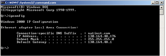
- Determine the IP address of the server machine: Go to Start » Run and type command, then press <Enter>. In the DOS window that appears, type ipconfig and press <Enter>. The IP address should appear listed in the window, along with some other network data. This DOS window is illustrated in the following figure.
- Go to Start»Program»National Instruments»NI-DAQ and select Remote Device Access Server to launch the server. If you want this computer to become an RDA Server every time it starts up, place a shortcut to the Remote Device Access Server in your Startup folder.
RDA Client Installation and Configuration
- Install LabVIEW 6.1 or another application development environment.
- If you chose not to install Traditional NI-DAQ (Legacy) in the previous step, install it now. Be sure that the same version of Traditional NI-DAQ (Legacy) is on both computers. If not, you might encounter the "Cannot Connect to Remote Server" error.
- Check the TCP/IP connection between the two computers. To perform this check, go to Start » Run and type ping and the IP address you obtained in Step 2 of the Server Installation and Configuration instructions. If you receive several lines of text that read "Reply from xxx.xxx.xxx.xxx bytes=..." then the network communication is working properly. Refer to the following figure for an illustration of this response.
Note: If this step fails, check with your network administrator. The remote device may be behind a firewall, so you will need to ask the network administrator how to access it.
- Launch Measurement & Automation Explorer (MAX). Right-click on Devices and Interfaces and choose Create New, then RDA/Ethernet Device, then click Finish. Next, in the dialog box that appears, type the IP address of the server computer, choose the device you want, and finally select a device number that is not currently used in this computer. The remote device should now appear listed under Devices and Interfaces in MAX. If you chose to install an SCXI system in the server, this will not appear in the client PC Devices and Interfaces list when you connect to the RDA Server.
- Test the resources of this new device to ensure it is working properly. If it passes the test, then the RDA setup is correct. To perform this operation, right-click the new device icon under Devices and Interfaces, and in the Configuration window, click the Modify Configuration... button. Refer to the following figure for an illustration of this step.
Note: You can also modify the configuration of the remote DAQ device from the client computer in another way. Launch MAX on the client computer, select
Tools option from the main menu bar, and then choose the
NI-DAQ Configuration»Remote DAQ Configuration. Type the IP address and password for the server into the dialog box that appears. Refer to the RDA Server and Installation instructions for information about determining the IP address. Next, a window titled Remote DAQ Configuration appears. This window displays the remote DAQ device, virtual channels, and SCXI chassis and modules. Though SCXI chassis and modules do not appear under Devices and Interfaces in MAX, they do appear here. When you select a device, virtual channel, or a SCXI chassis or module, the
Properties... button will be enabled. Clicking this button will enable you to modify the configuration of the remote devices. This feature is useful when the computers are far apart, and the SCXI chassis and module configuration must be changed from a central point.
Windows NT
RDA Server Installation and Configuration
- Install NI-DAQ 6.9.2 on the computer. Also, install and configure the DAQ device and the signal conditioning accessory, if you have one.
- Determine the IP address of the server machine: Go to Start»Run, type ipconfig and press <Enter>. The IP address should appear listed in the window, along with some other network data. This DOS window is illustrated in the following figure.
- Go to Start»Program»National Instruments»NI-DAQ and select Remote Device Access Server to launch the server. If you want this computer to become an RDA Server every time it starts up, place a shortcut to the Remote Device Access Server in your Startup folder.
RDA Client Installation and Configuration
- Install LabVIEW 6.1 or another application development environment.
- If you chose not to install Traditional NI-DAQ (Legacy) in the previous step, install it now. Be sure that the same version of Traditional NI-DAQ (Legacy) is on both computers. If not, you might encounter the "Cannot Connect to Remote Server" error.
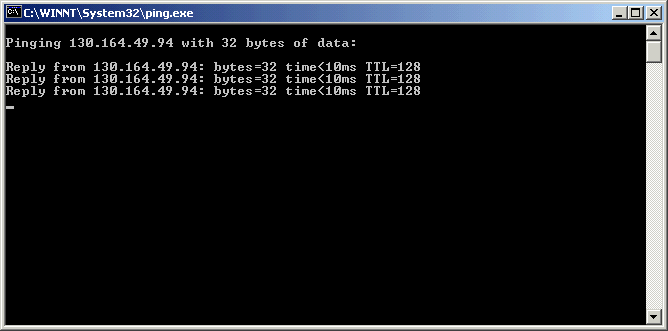
- Check the TCP/IP connection between the two computers. To perform this check, go to Start » Run and type ping and the IP address you obtained in Step 2 of the Server Installation and Configuration instructions. If you receive several lines of text that read "Reply from xxx.xxx.xxx.xxx bytes=..." then the network communication is working properly. Refer to the following figure for an illustration of this response.
- Note: If this step fails, check with your network administrator. The remote device may be behind a firewall, so you will need to ask the network administrator how to access it.
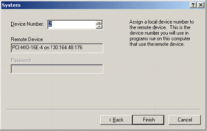
- Launch Measurement & Automation Explorer (MAX). Right-click on Devices and Interfaces and choose Create New, then RDA/Ethernet Device, then click Finish. Next, in the dialog box that appears, type the IP address of the server computer, choose the device you want, and finally select a device number that is not currently used in this computer. The remote device should now appear listed under Devices and Interfaces in MAX. If you chose to install an SCXI system in the server, this will not appear in the client PC Devices and Interfaces list when you connect to the RDA Server.
- Test the resources of this new device to ensure it is working properly. If it passes the test, then the RDA setup is correct. To perform this operation, right-click the new device icon under Devices and Interfaces, and in the Configuration window, click the Modify Configuration... button. Refer to the following figure for an illustration of this step.
Note: You can also modify the configuration of the remote DAQ device from the client computer in another way. Launch MAX on the client computer, select
Tools option from the main menu bar, and then choose the
NI-DAQ Configuration»Remote DAQ Configuration. Type the IP address and password for the server into the dialog box that appears. Refer to the RDA Server and Installation instructions for information about determining the IP address. Next, a window titled Remote DAQ Configuration appears. This window displays the remote DAQ device, virtual channels, and SCXI chassis and modules. Though SCXI chassis and modules do not appear under Devices and Interfaces in MAX, they do appear here. When you select a device, virtual channel, or a SCXI chassis or module, the
Properties... button will be enabled. Clicking this button will enable you to modify the configuration of the remote devices. This feature is useful when the computers are far apart, and the SCXI chassis and module configuration must be changed from a central point.
Windows 9x
RDA Server Installation and Configuration
- Install NI-DAQ 6.9.2 on the computer. Also, install and configure the DAQ device and the signal conditioning accessory, if you have one.
- Determine the IP address of the server machine: Go to Start»Run, type winipcfg and press <Enter>. The IP address and some other network data should appear in a window. Refer to the following figure for an illustration of this window.
- Go to Start»Programs»National Instruments»NI-DAQ and select Remote Device Access Server to launch the server.
RDA Client Installation and Configuration
- Install LabVIEW 6.1 or another application development environment.
- If you chose not to install Traditional NI-DAQ (Legacy) in the previous step, install it now. Be sure that the same version of Traditional NI-DAQ (Legacy) is on both computers. If not, you might encounter the "Cannot Connect to Remote Server" error.
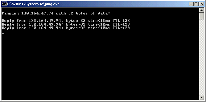
- Check the TCP/IP connection between the two computers. To perform this check, go to Start » Run and type ping and the IP address you obtained in Step 2 of the Server Installation and Configuration instructions. If you receive several lines of text that read "Reply from xxx.xxx.xxx.xxx bytes=..." then the network communication is working properly. Refer to the following figure for an illustration of this response.
- Note: If this step fails, check with your network administrator. The remote device may be behind a firewall, so you will need to ask the network administrator how to access it.
- Launch Measurement & Automation Explorer (MAX). Right-click on Devices and Interfaces and choose Create New, then RDA/Ethernet Device, then click Finish. Next, in the dialog box that appears, type the IP address of the server computer, choose the device you want, and finally select a device number that is not currently used in this computer. The remote device should now appear listed under Devices and Interfaces in MAX. If you chose to install an SCXI system in the server, this will not appear in the client PC Devices and Interfaces list when you connect to the RDA Server.
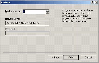
- Test the resources of this new device to ensure it is working properly. If it passes the test, then the RDA setup is correct. To perform this operation, right-click the new device icon under Devices and Interfaces, and in the Configuration window, click the Modify Configuration... button. Refer to the following figure for an illustration of this step.
Note: You can also modify the configuration of the remote DAQ device from the client computer in another way. Launch MAX on the client computer, select
Tools option from the main menu bar, and then choose the
NI-DAQ Configuration»Remote DAQ Configuration. Type the IP address and password for the server into the dialog box that appears. Refer to the RDA Server and Installation instructions for information about determining the IP address. Next, a window titled Remote DAQ Configuration appears. This window displays the remote DAQ device, virtual channels, and SCXI chassis and modules. Though SCXI chassis and modules do not appear under Devices and Interfaces in MAX, they do appear here. When you select a device, virtual channel, or a SCXI chassis or module, the
Properties... button will be enabled. Clicking this button will enable you to modify the configuration of the remote devices. This feature is useful when the computers are far apart, and the SCXI chassis and module configuration must be changed from a central point.
RDA Installation Considerations
- A computer can be both a RDA Server and a RDA Client at the same time. Furthermore, servers and clients can run a mix of Windows versions – 9x, NT, 2000, or XP.
- The NI-DAQ version for both the RDA Server and the RDA Client must match. If not, the network connection and transfer cannot occur.
- You can power on and off the RDA Clients without affecting the state of the RDA Servers to which the client has assigned local device numbers. Also, you can load and unload the Remote Device Access Server, but you must refresh MAX and click the Test Resources button to reconnect the remote device from the RDA Client to the RDA Server.
- If you assign a local device number to a remote device, Traditional NI-DAQ (Legacy) attempts to connect to the RDA Server each time it loads in the RDA Client. If the RDA Server is powered off, the RDA Client appears to stall during this process. This stalling is the timing out of the attempt to connect to the server computer. When the connection fails, any attempt to use the remote device will result in a -10340 (noConnectError) status error code, and you must repeat the configuration process.
- RDA Client programs should perform all clean-up activities on the remote device. Failure to do so can result in lost resources on the RDA Server and can cause unpredictable behavior.
- To access an SCXI module from a client PC through the RDA Server, you must use the device number that represents the RDA Device in MAX and use the channel given in the SCXI address form. This form is "ob0!scx!mdy!z," where x is this SCXI chassis number, y is the SCXI module number, and z is the channel number that you want to access on the SCXI module.
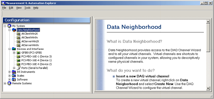
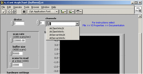
- Virtual channels can be used to address remote NI DAQ device channels as well as remote SCXI module channels. Moreover, these items can be installed at either the remote computer or the client computer. At the remote computer, they must be installed before the RDA configuration takes place. However, at the client computer, they must be set up after the RDA configuration. Furthermore, as already stated, the remote SCXI chassis and modules will not be listed under Devices and Interfaces in MAX on the client computer, yet when configuring virtual channels addressing remote SCXI modules, they will be listed in order to be addressed in the configuration wizard from the client computer. The following two figures show the difference between how the virtual channels are presented in MAX and LabVIEW.
Benchmark Test Overview
The following benchmark tests were performed to demonstrate the RDA feature provided by NI-DAQ 6.9.2 under LabVIEW 6.1. For performing these tests, the following hardware was used:
The results from these benchmark tests may vary depending upon the computer and the DAQ devices used, the number of applications running during the acquisition on both the remote and client computers, and the data processing performed by each application.
Benchmark Tests
Benchmark Test 1
Use Cont Acq&Chart(buffered).vi to scan channel 1 of the RDA Server. The results were max scan rate = 220 kS/s, with a buffer of 50 kS, reading 10 kS at a time.
Benchmark Test 2
Use Cont Acq&Chart(buffered).vi to scan channels 1 and 2 of the RDA Server. The results were max scan rate = 130 kS/s, with a buffer of 50 kS, reading 10 kS at a time.
Benchmark Test 3
Use Cont Acq&Chart(buffered).vi – modified for two devices – to scan channels 1, and 2 of the RDA Server and channel 1 of RDA Client. AT the server, the results were max scan rate = 70 kS/s, with a buffer of 50 kS, reading 10 kS at a time. At the client, the results were max scan rate = 120 kS/s, with a buffer of 50 kS, reading 10 kS at a time.
The figure below shows how VI Logger can be used with RDA.