Prerequisites
Hardware and Software Installation
- Install LabVIEW, LabVIEW Real-Time (if required), and NI-VISA.
- Before installing hardware, ensure your PXI chassis is switched off and unplugged.
- Install the DF PROFINET IO board in the PXI chassis.
- Plug in the chassis and turn it on.
- By default, the green LED above port 1 (controller port) will be lit. (LEDs description )
- Install the PROFINET for PXI driver following the instructions on the download page.
- Associate the board driver software with the hardware by first opening Device Manager
- In Windows 7, go to your control panel and open the Device Manager.
- In Windows 10, right-click Start (Windows Symbol) in the taskbar and open Device Manager
- Find the entry named PowerPC-Processor in list, as shown in Figure 1.
- Right-click the PowerPC entry and select Update driver software, also shown in Figure 1.
- Choose the option to browse your computer for driver software.
- Find and select the file C:\Users\Public\Documents\KUNBUS GmbH\INF\DFPNIO_NIVISA.inf
- After driver installation, the card should display as "DF PROFINET IO" in Device manager (Figure 2).
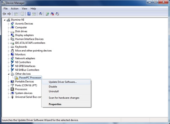
Figure 1: Device Manager before driver association

Figure 2: Device Manager after driver association
After Hardware and Software Installation open Measurement & Automation Explorer (MAX) and check for proper installation of the DF PROFINET IO board, as shown in Figure 3.
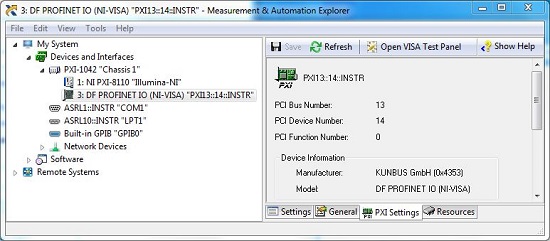
Figure 3: A correctly installed DF PROFINET IO card in MAX.

Figure 4: Incorrect recognition - if your board looks like this in MAX, close and reopen MAX. If it still looks like this, check the driver association in Device Manager starting on step 6, above.
Real-Time Installation Considerations
Remote Software Installation
- Find your PXI controller under Remote Systems in NI MAX and expand it.
- Right-click Software and select Add/Remove Software.
- When selecting the software you want to install, make sure to check KUNBUS DF PROFINET IO – RT.
- You can confirm your hardware is recognized by expanding Devices and Interfaces under your PXI Controller.
Configuring Remote Access to VISA Resources
- Under the remote RT system in NI MAX, expand Software and click NI-VISA.
- Click the VISA Options tab at the bottom of the window.
- On your host PC, click Security under VISA Server.
- Click inside the Remote Access List and add the IP address of your PC.
- Under My System (for your local PC), expand Software and click NI-VISA.
- Click Remote under VISA Settings.
- In the list of Remote Devices, select your PXI controller.
- To test, close and reopen MAX, then go to Tools >> NI-VISA >> VISA Interactive Control.
- Select your remote PXI system in the drop-down list.
- If the wizard discovers the DF PROFINET IO card, this setup step was successful. If not, restart both systems and follow the steps in this section again.
PROFINET Controller (Master) Configuration
Before using the DF PROFINET IO as a controller on Port 1, you need to create a configuration which describes the PROFINET network. This configuration is created using the KUNBUS configuration tool Configurator III. Configurator III allows you to create the complete PROFINET IO configuration based on Device GSDML files. Refer to the Configurator III help for details.
Start Configurator III from Start >> All Programs >> Kunbus GmbH >> Kunbus Configurator. From the Project Menu choose “New” to create a new PROFINET configuration. Then, drag and drop a DF PROFINET IO controller board to the configuration window as shown in Figure 5.
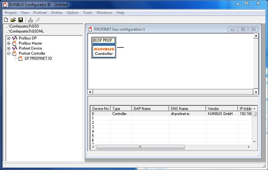
Figure 5: Configurator III Controller Part
From the Online Menu choose “Driver selection” and press “Search...” to update the selection window as seen in Figure 6. Choose your controller board or controller alias and press OK.
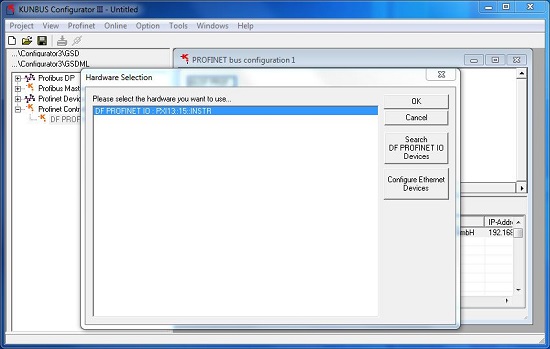
Figure 6: Configurator III Controller Selection
PROFINET Slave Configuration
If using a slave device from another vendor, you can import the descriptor file to Configurator III by going to Tools >> Install new PROFINET/GDSML XML-file.
As an example, we will configure a loopback with Port 2 of the DF PROFINET IO as the device and Port 1 as the controller. If you are using a 3rd-party device, the steps to configure the device will be similar. From PROFINET Device >> IO drag and drop a DF-Profinet-IO device board to the configuration window as shown in Figure 7.

Figure 7: Configurator III Slave Part
From the In/Out Modules configuration list drag your device memory configuration to Slot 1 as shown in Figure 8.
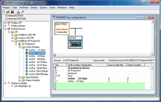
Figure 8: Configurator III device memory configuration
Press the Download button in the menu bar as seen in Figure 9. The “Project save” dialog appears if the document has not been saved. Name your project and save it to the configurator projects folder. Wait until the download has finished successfully.
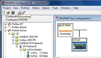
Figure 9: Configurator III configuration download
DF PROFINET IO Device (Slave) Configuration with 3rd Party Controller
The DF PROFINET IO interface card comes with a typical PROFINET IO Device description file (GSDML file), which is located in the folder C:\Users\Public\Documents\KUNBUS GmbH\GSDML
The GSDML file is used to configure the DF PROFINET IO Device on the related PROFINET IO Controller (i.e. a PLC). To configure the DF PROFINET IO device, import the GSDML file into the related PROFINET IO Controller configuration tool that comes with your controller.
The GSDML file offers several modules with different data sizes for input- output- and combined inputs/outputs, which can be used to configure the DF PROFINET IO module.
The DF PROFINET IO device supports shared Device operation mode, which means that multiple PROFINET IO controllers can access different slots of the DF PROFINET IO device simultaneously. For the proper configuration of shared devices, refer to the relevant user manual of the PROFINET IO controller configuration tool.
For operation as a device, use Port 2 on the card.
Programming in LabVIEW
You can find KUNBUS PROFINET IO VIs in the functions palette under Industrial Communicatons>>KUNBUS GmbH>>DF PROFINET IO.
To find Examples, Use Help>>Find Examples. Navigate to Toolkits and Modules>>Third-Party Add-Ons>>KUNBUS GmbH>>PROFINET. Here you can find the example DF PROFINET IO GettingStarted.lvproj.
To continue the loopback example from above, open both the DF PROFINET IO GettingStarted Controller.vi (Controller.vi) and DF PROFINET IO GettingStarted Device.vi (Device.vi). For both VIs, select your DF PROFINET IO card from the "PROFINET..." dropdown box in the upper left of the Front Panel. In Device.vi, set "Slot" to -1.
Start Controller.vi first, then start Device.vi. They might initially display a bad APDU status (0x21 on Controller.vi and 0x00 on Device.vi) as both get set up. The APDU status for normal operation is 0x35, and the green and yellow LEDs should be on beside the physical card ports.
Send data from the Controller.vi to the device by entering it into "Modify Output Data" and clicking "Set output data." You should see it show up on the Device.vi's "Output data" indicator as seen in Figure 10.
You can send data from the device to controller by entering it in Device.vi's "Modify input data" and clicking "Set input data", also in Figure 10.
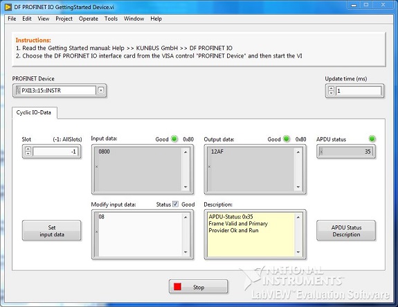
Figure 10: DF PROFINET IO GettingStarted Device.vi example after sending and receiving data.