Enable the Vision Builder Ethernet/IP Server
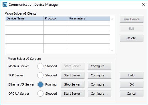
Launch Vision Builder AI if it is not already open. Create a new inspection or open an existing inspection. To enable the Vision Builder AI Ethernet/IP server, open the Communication Device Manager by clicking Tools>>Communication Device Manager. Click the Start Server button next to the Ethernet/IP Server.
Configure the Assembly Size
By default, Vision Builder AI assemblies are 500 bytes for the input assembly and 496 bytes for the output assembly. Some PLCs do not support assemblies that large. For example, the Omron CJ2M CPU31 version 2.0 only supports assembly sizes of 40 bytes, while version 2.1 and later removed this limitation.
Refer to the documentation of your PLC to verify the maximum size of the assembly it supports.
Use the Vision Builder AI Communication Device Manager to change the assembly size. If it is not still open, select Tools>>Communication Device Manager in Vision Build AI. Click the Configure button for the Ethernet/IP Server and change the size of the assemblies. You will also need to configure the Input and Output Registers that you wish to communicate to and from the PLC.
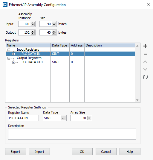
Click OK to reboot the Ethernet/IP server with the new assembly sizes. Click OK to close the Communication Device Manager window.
Configure the EDS File
Download the attached NI Vision Builder AI.eds file attached to this tutorial and open the file in a text editor. You will need to edit the input and output assembly sizes in this folder to match what you configured in the Communication Device Manager. The relevant section in the file is lines 67-82.
For example, if I had set my input and output assemblies to both be 40 bytes, those lines should look like this:
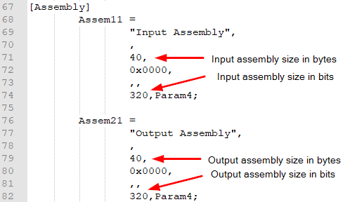
Please note that not only do you need to set the assembly size to be 40 bytes, but also set the corresponding number of bits for the assembly (320 in this case).
Alternatively, you can use a tool like EZ-EDS that you can download from the ODVA web site to configure the assembly size and ensure the EDS file is properly formatted.
Once the EDS file is configured and saved, copy the file to the following folder:
C:\Program Files (x86)\OMRON\Sysmac Studio\IODeviceProfiles\EipConnection\Eds
Configure Sysmac Studio
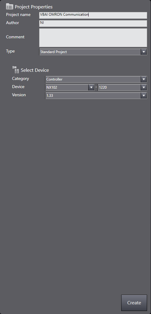
Open Sysmac Studio and create a new project. Configure the project name and device that you are using.
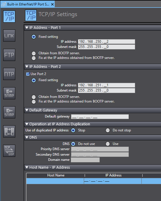
Configure the EtherNet/IP settings for the PLC by going to Configuration and Setup»Controller Setup»Built-in EtherNet/IP Port Settings. Specify the IP address settings for Port 1 of the PLC controller. The IP address and subnet mask should be configured so that the PLC is on the same subnet as the Vision Builder AI computer or remote target.
Next, create the variables to hold the data for the EtherNet/IP communication. Go to Programming»Data»Global Variables. Create new global variables and set the data types to match the assembly data registers that you previously configured in Vision Builder AI.
Tip: Under Data>>Data Types, you can create data types that match the assembly structure defined in VBAI and set the datatype of the variable to this data type.
For the sake on simplicity in this tutorial, we will set the variables to ARRAY[0..39] of BYTE, which matches what we configured in Vision Builder AI.
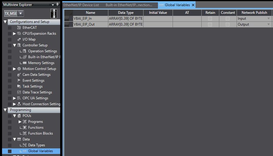

When you create the variables in Sysmac Studio, the size needs to match assembly size that is configured in Vision Builder AI. Make sure to set Network Publish as input or output which should match how it is configured in the Ethernet/IP Assembly Configuration in Vision Builder AI.
Configure Ethernet/IP Connections Settings
- Go to Tools»Ethernet/IP Connection Settings in Sysmac Studio.
- Right-click on the port connected to the Vision Builder AI device and click Edit.
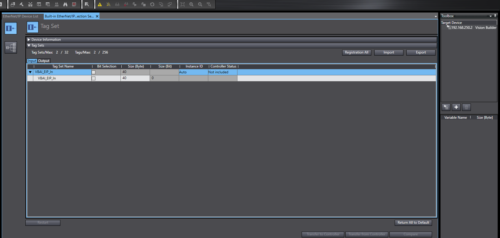
- Right-click in Tag Sets and select Register All Tag Sets. This should find the variables. Click Register.
- Set the Instance ID to 101 for the input, 102 for the output (or however you have configured it in VBAI).
Add Connection to Vision Builder AI
- Click the Connection button.

- We need to add the VBAI target device. Click Add a target device in the Toolbox window.
- Set the Node address to be the IP address of the Vision Builder AI target device
- Select NI Vision Builder AI in the Model name dropdown. If it doesn’t show up in the dropdown, it’s because you didn’t copy INI file to the correct location in the Configuring the EDS File section.
- Set the Revision to 2.
- Click Add to finish adding the device.
- Now that the NI Vision Builder AI device is added, drag it from the Target Device list into the Connections window.
- Set the Connection I/O to “Consume Data From/Produce Data To”
- Set Target Variable to 101 for Input, 102 for Output.
- Set Size [Bytes] to 40 for both input and output.
- Set the Originator Variable to the variables previously defined in Data»Global Variables.
- Set the Input Originator Variable to VBAI_EIP_In
- Set the Output Originator Variable to VBAI_EIP_Out
Go Online with the Ethernet/IP connection to Vision Builder AI
- Click the Go Online button.
- Click the Synchronize button.
- In the Synchronization window, uncheck the checkbox Do not transfer the Ethernet/IP connection settings (i.e. data link Settings).
- Click Transfer to Controller.
- Click Yes to execute the transfer.
- Click Yes to change to operating mode to run mode.
- Click Close to close the Synchronization dialog.
- We should now be online and connected to VBAI.
Confirm Connection to Vision Builder AI
To confirm that the connection is setup, go back to the Ethernet/IP Device List tab, right click on the port 1, and select Monitor.
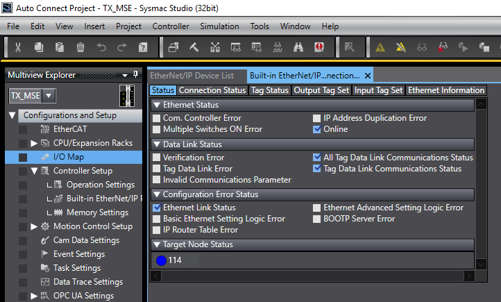
If the communication is successful, the Target Node Status will be blue.
If the Target Node Status is red, a communication error has occurred. Select the Connection Status tab to find the status error. You can look up the status error in the Ethernet/IP Error Code Decoder to determine why the connection is failing.
If a connection has been established, click on the Watch (Table) tab icon to display the watch table.
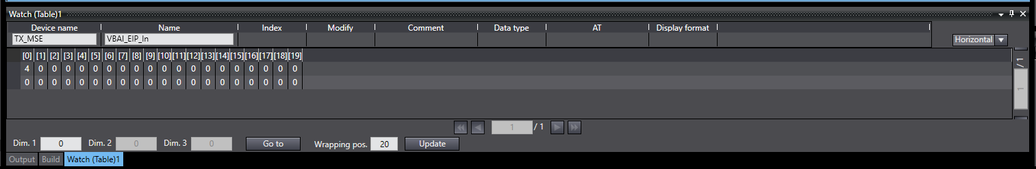
Enter the variable name corresponding to the input assembly and verify that VBAI can write to it.
Enter the variable name corresponding to the output assembly, type some number and verify that VBAI properly reads that number.