How to Get Started with NI-XNET and NI VeriStand
NI VeriStand provides a framework for real-time testing applications such as embedded software validation and real-time control and monitoring of mechanical test cell applications. The NI-XNET family of products includes a series of high-performance CAN, LIN, and FlexRay interfaces. These interfaces are optimized for applications that require real-time, high-speed manipulation of hundreds of CAN, LIN, and FlexRay frames and signals, such as HIL simulation, rapid control prototyping, bus monitoring, automation control, and more. This section will go through the installation process, configuring the VeriStand environment, and setting up NI-XNET ports and databases.
NI VeriStand Software Installation
To get started with NI-XNET and NI VeriStand, the first step is to ensure the correct software is installed on the computer and the target is in the proper order. Go through the first two steps of the section entitled New Installation in the Installation Order for Multiple NI Software Products knowledge base to start the setup of the system. As a note, the NI LabVIEW Development Environment is not required for all hardware platforms. If the hardware platform that is being used doesn’t require NI LabVIEW, go to the next step. There are some notes included in this section below based on the hardware in the system.
NI CompactRIO Platform
- The LabVIEW development system is required.
- The FPGA Module must be installed.
- The NI-RIO driver must be installed.
Real-Time Target
- The LabVIEW Real-Time Module must be installed.
After the first two steps are completed, the next step is to complete the installing software sections the Getting Started with VeriStand 2021 tutorial to complete the setup of the system based on the hardware in the system.
All Hardware Platforms
- The NI-XNET driver must be installed.
NI VeriStand Project Setup
NI VeriStand uses projects to help get up and running quickly. To set up the project correctly and understand all the available options, complete the Create a Project section in the Getting Started with NI VeriStand tutorial.
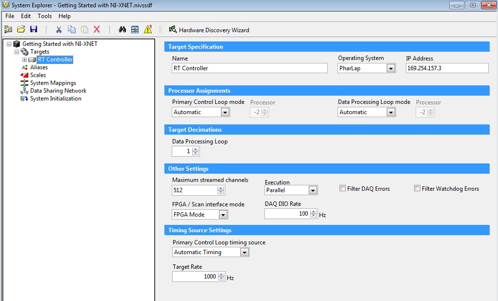
Figure 1. The controller specification screen enables NI VeriStand to communicate with the appropriate device and at the specified target rate.
Configure the NI VeriStand Engine and Project with NI-XNET
When the NI-XNET driver software is installed with NI VeriStand, an extensive set of NI VeriStand features are enabled that support communicating with hardware over the CAN, LIN, and FlexRay protocols. It may be helpful to understand NI-XNET related concepts and terminology in NI VeriStand before getting started by going through the Using NI-XNET, CAN, LIN and FlexRay Interfaces NI VeriStand Help.
There are many different configuration options available in NI VeriStand based on the hardware in the system. The sections below discuss the platforms that are available with NI-XNET. Select the appropriate hardware target to set up the NI VeriStand project for execution.
NI CompactRIO Targets
A custom FPGA bitfile must be compiled to use a NI 986x XNET module because the NI 986x XNET module doesn’t work in scan mode on the NI CompactRIO. There are two ways to perform NI-XNET communication with the NI 986x XNET module on the NI CompactRIO: FPGA mode or hybrid mode. This section will focus on the steps to get started with the NI 986x XNET module in FPGA mode. If the NI CompactRIO target has other NI C series modules in scan mode, the NI 986x XNET module can be used in hybrid mode. More information and implementation steps for hybrid mode are available in the NI VeriStand Add-On - Scan Engine and EtherCAT community page.
FPGA Mode
NI LabVIEW is required to use FPGA mode on the NI CompactRIO for the NI XNET 986x module. Below are the steps that will need to be followed to successfully set up the NI 986x XNET Module for use in NI VeriStand. The first eight steps are completed in NI LabVIEW and the last two steps are completed in NI VeriStand.
1. Create a blank NI LabVIEW project.
2. Add an NI CompactRIO target.
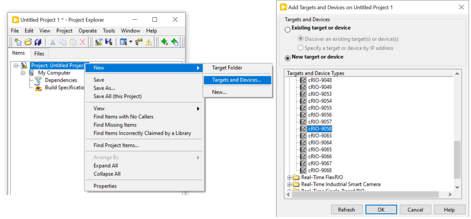
Figure 2. To specify the hardware in the system, add the NI CompactRIO target to the NI LabVIEW project
3. Add an FPGA Target.
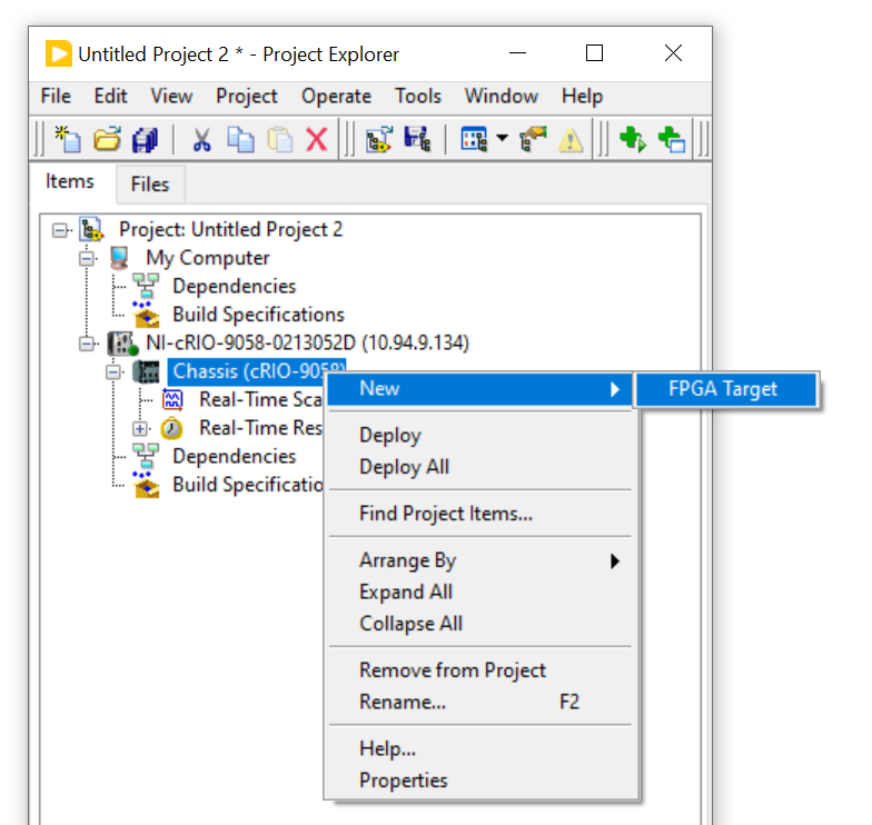
Figure 3. Add an FPGA target to the NI LabVIEW Project to set up the NI-XNET communication.
4. Add an NI 986x XNET Module.
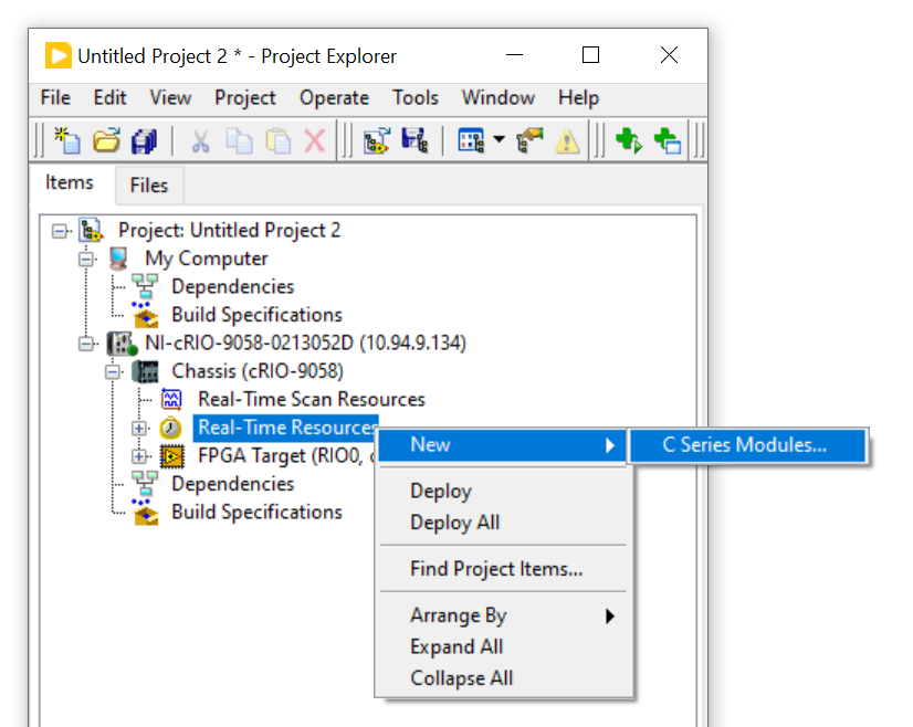
Figure 4. Add an NI 986x XNET module to the NI LabVIEW project.
5. Add a Blank VI to the FPGA Target.
6. Save the VI.
7. Save the project.
8. Compile VI.
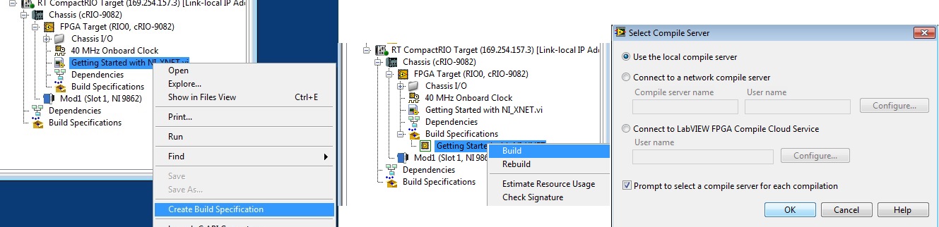
Figure 5. Create a bitfile to use in NI VeriStand by compiling the VI in the NI LabVIEW project.
9. Add CAN or LIN port.
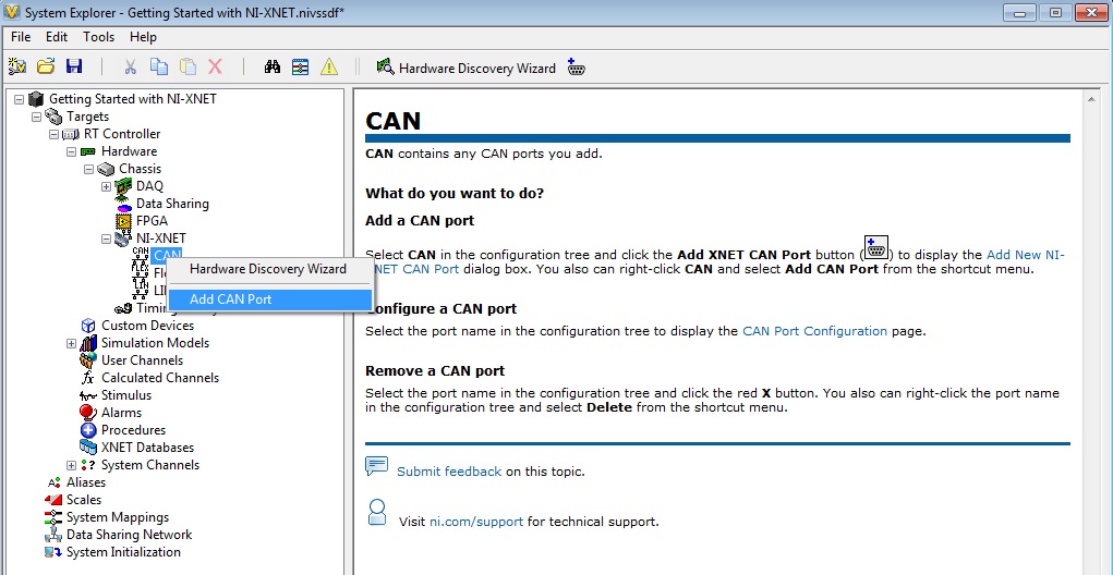
Figure 6. Add NI-XNET port to NI VeriStand.
10. Add the bitfile to the port that was created.
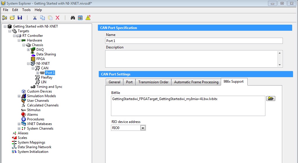
Figure 7. Add the bitfile to the communication port.
NI PXI/PCI/CompactDAQ
Adding a CAN, LIN, or FlexRay Port
An interface represents a single CAN, LIN or FlexRay connector on an NI hardware device. NI-XNET also uses the term port to refer to the connector on an NI hardware device. Configure a NI-XNET session in NI VeriStand by simply adding ports under the appropriate protocol. To add a port to NI VeriStand, follow the steps in Adding NI-XNET Devices NI VeriStand Help for your appropriate NI-XNET device.

Figure 8. Add NI-XNET Port to NI VeriStand.
Once the appropriate NI-XNET port has been added, configure additional settings for the port through the protocols configuration page.
Add a NI-XNET Database to NI VeriStand
For the NI-XNET interface to communicate with hardware products on the external network, NI-XNET must understand the communication in the actual embedded system, such as the vehicle. This embedded communication is described within a standardized file, such as a CANdb (.dbc) for CAN, FIBEX (.xml) for FlexRay, or LIN description file (.ldf) for LIN. Within NI-XNET, this file is referred to as a database. Complete the steps in the Adding NI-XNET Databases NI VeriStand Help to add a database in NI VeriStand. An example database can be found at <Public\Documents\National Instruments\NI-XNET\Examples>.
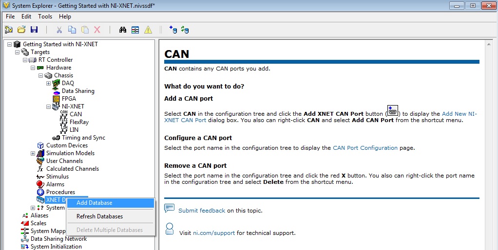
Figure 9. Add a database to NI VeriStand for NI-XNET to interpret the communication in the embedded system.
Once you have added your database, you can select the database on the NI-XNET Port configuration page.
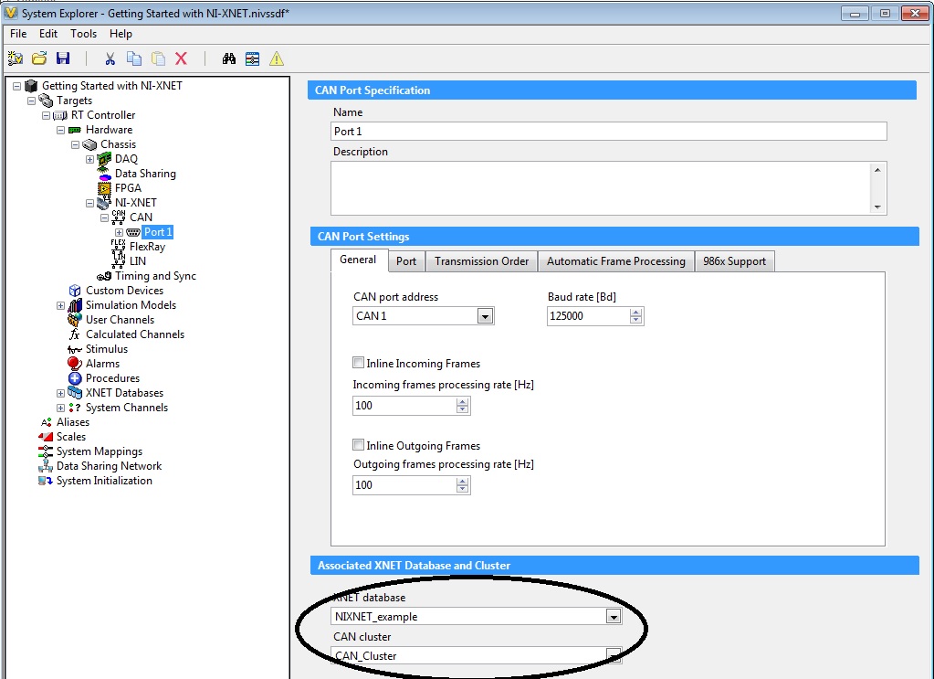
Figure 10. Associate the appropriate database (demonstrated in the circle) to the NI-XNET port that has been created.
Edit a Database from NI VeriStand
Now that the database has been added, the NI-XNET Database Editor can be used to edit the database directly from NI VeriStand. The NI-XNET Database Editor is a small standalone tool for creating and maintaining embedded network databases. The editor is used to configure the basic network, define frames and signals exchanged on the network and assign frames to ECUs that send and receive them. Launch the NI-XNET Database Editor by following the Editing NI-XNET Databases NI VeriStand Help.
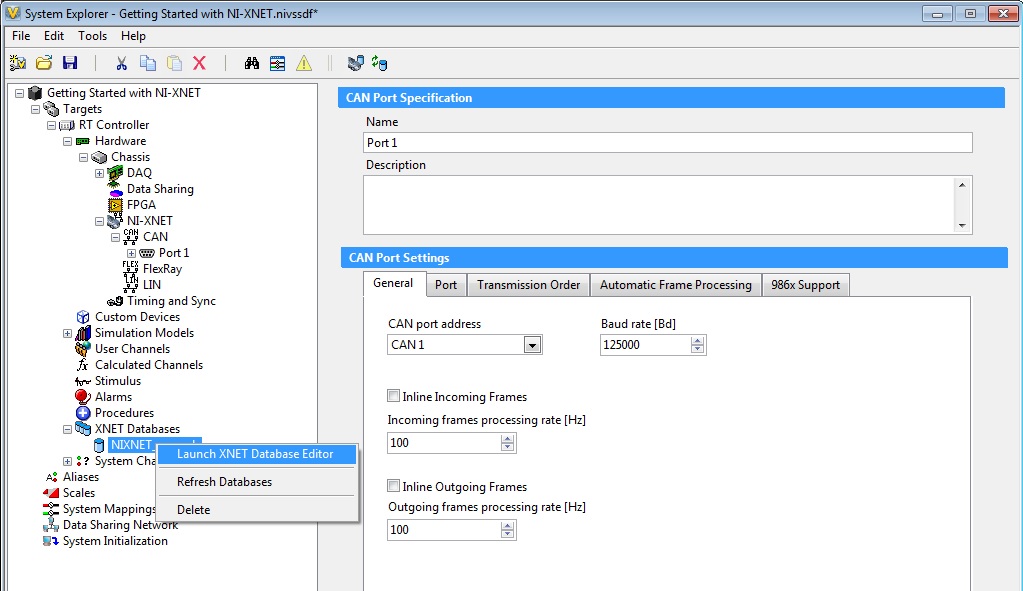
Figure 11. Launch the NI-XNET Database Editor to edit databases directly in NI VeriStand.
If you want more information on how to use the NI-XNET Database Editor, refer to the FIBEX and the NI-XNET Database Editor Overview whitepaper.
Importing Frames into NI VeriStand
Frames are messages transmitted across an embedded network. These messages are sorted into clusters with a database. In NI VeriStand, frames can be either inputs (incoming frames) or outputs (outgoing frames). Follow the steps in the Importing NI-XNET Frames NI VeriStand Help to import your NI-XNET frames into NI VeriStand after the NI-XNET database has been added.
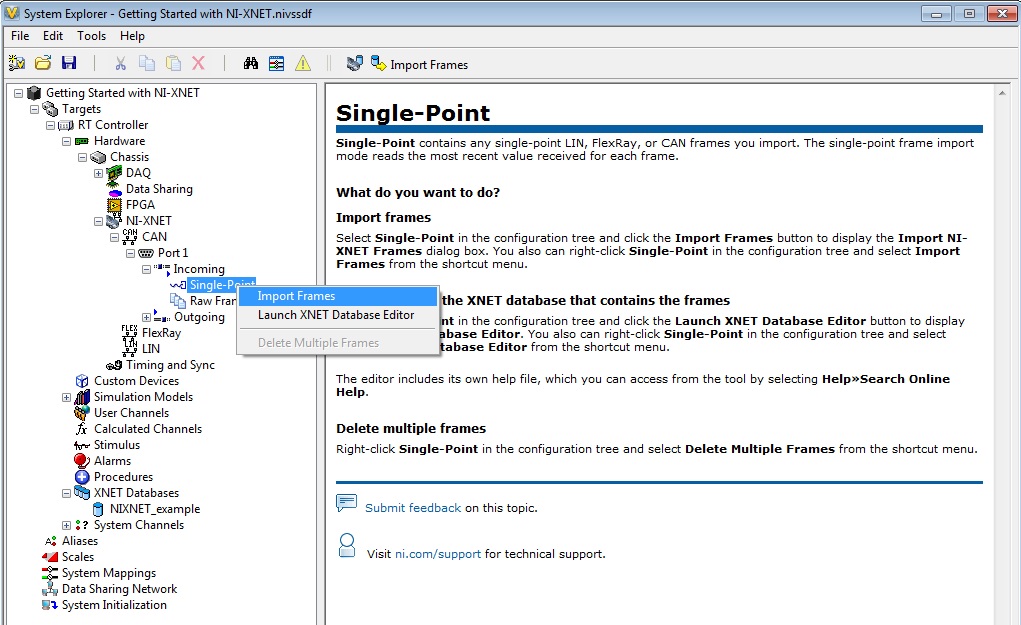
Figure 12. Import frames into NI VeriStand.
Additional Resources for NI-XNET and NI VeriStand
Below is additional information that could be useful while using NI-XNET with NI VeriStand.
Onboard and Software Selectable Termination
Since termination is different depending on what protocol is being used, please refer to the CAN Physical Layer and Termination Guide to ensure that the setup is correctly terminated. This whitepaper will go into the theory of termination and provide all the necessary termination information.
NI VeriStand Loopback Test with NI-XNET
The video in the section entitled NI-XNET CAN, LIN, and FlexRay Interfaces of the CAN, LIN, and FlexRay Interfaces for NI VeriStand whitepaper demonstrates how to perform a loopback test with a PXI Real-Time target and the CAN communication protocol. The setup is almost identical regardless of whether or not it is a NI CompactRIO target or a PXI Real-Time target. The main difference is in the NI VeriStand project setup phase. Ensure the appropriate steps are being followed for the NI CompactRIO chassis.
Accessing Timing and ID Information for Incoming NI-XNET Frames
In NI VeriStand, frame Information channels store information about incoming NI-XNET frames. The following three types of Frame Information channels can be accessed: receive time, time difference and frame ID. Complete the following steps in the Accessing Timing and ID Information for Incoming NI-XNET Frames NI VeriStand Help to create Frame Information channels.
Accessing Faulting Channels and Disable and Trigger Channels for Outgoing NI-XNET Frames
Being able to specify skipping cyclic frames and determining the transmit time of a cyclic frame can be important. Complete the following steps in the Configuring Cyclic Frame Faulting NI VeriStand Help to create frame faulting channels.
In NI VeriStand, outgoing frames can be disabled and triggered through the signal frame configuration page.
How to Get Started with NI-XNET and NI LabVIEW
NI LabVIEW gives you a single environment in which to acquire, analyze, and present your data and it abstracts low-level programming calls. NI LabVIEW gives the ability to completely customize your stand-alone measurement system. As described in the NI VeriStand introduction above, the NI-XNET platform includes a series of high-performance CAN, LIN, and FlexRay interfaces. These interfaces are optimized for applications that require real-time, high-speed manipulation of hundreds of CAN, LIN and FlexRay frames and signals, such as HIL simulation, rapid control prototyping, bus monitoring, automations control and more. Review this section of the article to get started with NI LabVIEW and NI-XNET.
NI LabVIEW Software Installation
To get started with NI-XNET and NI LabVIEW the first step is to ensure the correct software is installed on the computer and the target. Go through the New Installation section of the Order of Installation for Multiple NI Hardware and Software Products knowledgebase to set up the system properly. There are some notes included in this section below based on the hardware in the system.
All Hardware Platforms
- The NI-XNET driver must be installed.
NI CompactRIO Platform
- The FPGA module must be installed.
- The NI-RIO driver must be installed.
Real-Time Target
NI LabVIEW Setup
NI LabVIEW is a development environment for problem-solving, accelerated productivity, continual innovation and is ideal for any measurement or control system. To use NI LabVIEW with the NI-XNET driver, go through the Fundamentals of Using the NI-XNET API for LabVIEW whitepaper. This whitepaper will go through a basic programming example up to creating an application.
To help with the getting-started process, NI LabVIEW provides examples for NI-XNET. When the LabVIEW start menu is available, choose Find Examples from the NI LabVIEW Help menu.
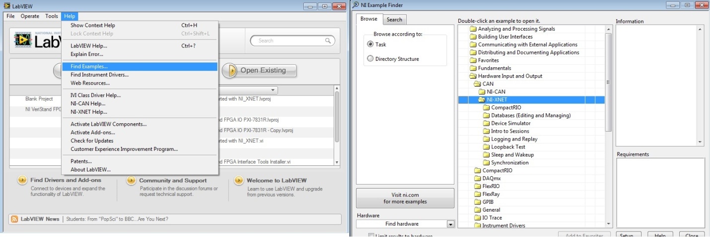
Figure 13. The NI-XNET examples provide great references or starting points.
Browse examples by task, NI-XNET examples are under Hardware Input and Output. The examples are grouped by protocol in CAN, FlexRay and LIN folders.
NI CompactRIO Targets
A bitfile is required to use the NI XNET module with NI CompactRIO in NI LabVIEW. There are eight steps to create a bitfile and is mentioned earlier in this paper under the FPGA Mode section of NI CompactRIO targets. After compilation is completed, run the Blank FPGA VI at least once to load the XNET communication logic to the FPGA.