Using Connection Diagrams through Measurement & Automation Explorer
Once you have a NI-DAQmx task defined in Measurement & Automation Explorer (MAX), you can open the connection diagram by clicking on the Connection Diagram tab next to the NI-DAQmx Task tab towards the bottom of the screen. Refer to figure 1 for more information on the location on this tab.
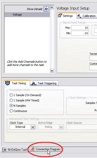
Figure 1: Connection Diagram Tab in MAX
When you click on the Connection Diagram tab, depending on the specific task and the associated hardware configuration, a wiring schematic will be automatically created for you. In the following example (figure 2), a simple analog input voltage task was created for a PCI-6259 using channel 0. A terminal block (SCB-68) is connected to the data acquisition board as a simple accessory and Non Referenced Single Ended was chosen as the terminal configuration for this particular task.

Figure 2: Sample Connection Diagram for an Analog Input Voltage Task
Using Connection Diagrams through DAQ Assistant
If you are using a DAQ Assistant to configure your data acquisition task, then you can follow similar directions as mentioned previously to open up the connection diagram for that specific task. In the figure below, a connection diagram for wiring a strain gauge has been illustrated. The task uses a SCXI-1000 chassis with a SCXI-1520 module and a SCXI-1314 terminal block. The task has been configured from a full bridge type-I strain gauge with internal excitation.
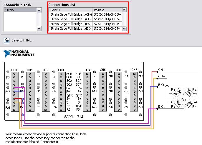
Figure 3: Sample Connection Diagram for a Strain Gauge Input Task
As you would notice, the connection diagram gives out a wiring schematic and also a list the actual terminals. From the connection diagram tab, you can also generate a HTML file corresponding to the current diagram by clicking on the Save to HTML button, which can be printed out or referred later.
Conclusion
Connection diagrams provide a quick and a reliable way to access the wiring schematic for a particular DAQmx task. A connection diagram could be accessed either through MAX or DAQ Assistant.