Visualizing the Instruments
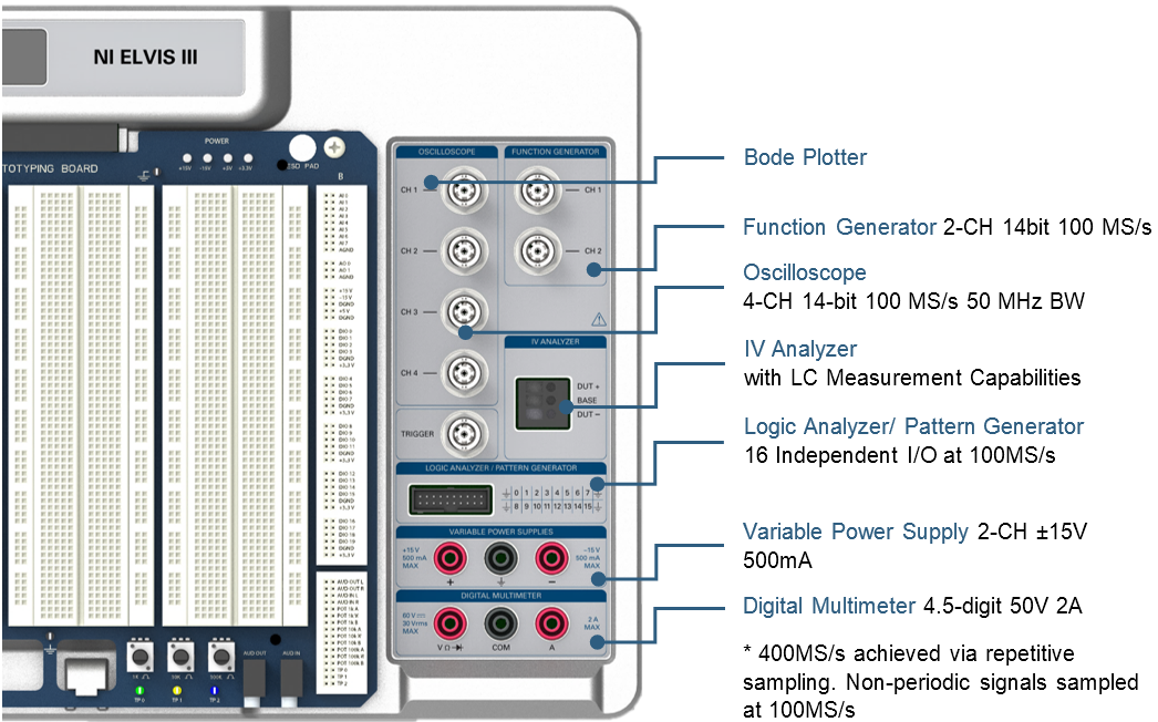
NI ELVIS III contains 7 benchtop instruments all in one device. These instruments contain everything a student might need to design and analyze a circuit or instrument a system. For a helpful visualization of the instruments and specifications of instruments on NI ELVIS III, see the image below:
Common Troubleshooting Techniques Using NI ELVIS III
One of the most common use-cases of the NI ELVIS is troubleshooting circuits, projects, and large systems to discover how to fix unexpected results and ultimately learn along the way.
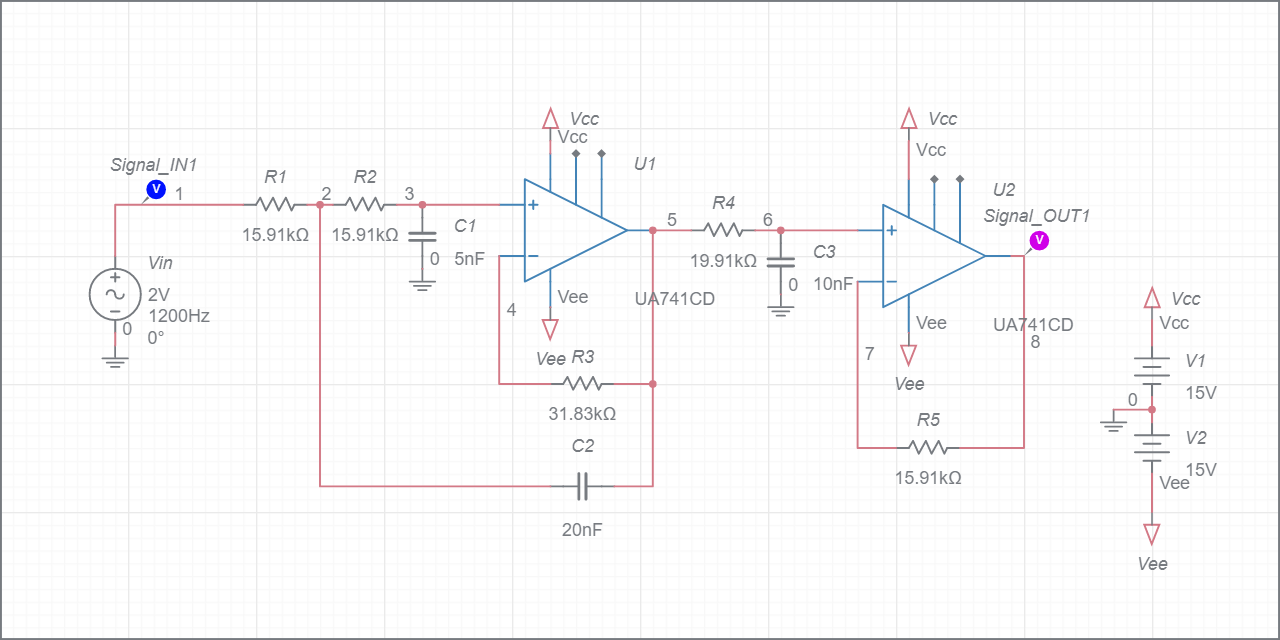
Consider the 3-stage low pass filter below:
Unexpected Filter Roll-off
- Verify each stage of an LPF contributes to a decay in magnitude of 20 dB/ dec once the input exceeds the cut-off frequency (ωc)
- Conduct frequency response analysis for each stage and see if each stage has a roll off rate of -20 dB/dec using the Bode analyzer
- Pay attention to whether the roll off is positive or negative. LPF needs all stages to be negative/ decay. A positive roll-off means it is a high pass filter which works as a band pass filter when operated as a stage within an LPF
- If a stage’s frequency response shows no desirable change around ωc, then check the value of each passive and active component by using the DMM to confirm resistance or capacitance
Unexpected Cutoff Frequency
- For each stage, verify that R and C were chosen to give the same ωc value. When different stages have differing cut-off frequencies, the least value will apply to the entire LPF
- Once you have visually verified the R and C values, use a DMM to measure the R and C components are as indicated and are in working condition
- Parasitic capacitance appearing parallel or in series with circuit capacitors can lead to a deviation from the expected cut-off frequency, try to see how far off your actual cut-off frequency is from the theorized and switch components to account for the added paracitic capacitance
Attention Not Consistent with Simulation
- Test if the operational amplifiers are working as expected, measure the output with the oscilloscope or verify the variable power supply is set correctly for the required voltages of the operational amplifier
- Check the output of each Op-Amp against a known input voltage and gain using the function generator and oscilloscope
Multisim Live may be used in conjunction with NI ELVIS III to simulate circuits before physically building them.
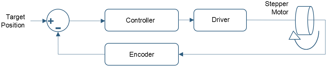
Now, consider a simple control system for a stepper motor:
Motor Doesn't Turn On
- Check if the motor is getting enough power. If the controller power supply is not able to deliver enough current to the motor, it may cause a voltage drop in the system. This can lead to sensor dropouts and even controller reset. Confirm the power is being appropriately supplied by checking the voltage and current using the DMM. You can fix this by powering the motor using the variable power supply in the Instrumentation Panel.
- Check if the torque is too low for the set starting speed. Refer to the motor specifications sheet to determine the maximum no-load starting speed and set it accordingly.
- Make sure all the connections have continuity. If the motor has 6 wires, then there will be 2 pairs of wire with a common wire for each pair. Use the DMM on the NI ELVIS III to identify the common wire(s) and connect them to the positive terminal of the power supply. Then manually connect the remaining wires to the ground one by one in sequence. The motor should jump a little each time you change wires. If there is no movement, then the motor may have failed.
Motor Turning Erratically
- Check to see if the phases of the motor are reversed.
- Ensure that your encoder is returning expected results. This can be done by, in software, probing the data out of the counter that is reading the encoder and watching the position. Then, manually turn the motor shaft 360 degrees. The encoder should read back a number equal to the ticks per revolution specified in the specifications document.
- Confirm that the PID controller is sending appropriate commands. Try setting the I and D terms to zero so that only the P term has any interaction with the system. If that corrects the behavior, then the controller needs to be either retuned or has a coding error.
Motor Not Working in Circuit
- Check for driver failure: This can happen when the peak voltage is not controlled and damages the driver. Use a DMM to probe the driver or use the function generator to input a known value then probe the output with an oscilloscope to check for appropriate behavior.
Circuit / Motor Making Noise
- There are no loose parts and the motor bearings are not worn.
- The gain setting on the controller is not too high. The gain of the speed controller determines how much torque the drive will generate. Consequently, the gain value should be directly proportional to the inertia of the load of the motor.
Motor Not Turning Accurately
- Double check the connections coming in and leaving the controller, including its power supply
- Ensure that your encoder is returning expected results. This can be done by, in software, probing the data out of the counter that is reading the encoder and watching the position. Then, manually turn the motor shaft 360 degrees. The encoder should read back a number equal to the ticks per revolution specified in the specifications document.
Motor Never Reaches Setpoint
- Set all gains to zero.
- Set P gain to a small value (1 or less) and watch for the signal to oscillate with a proportional gain.
- Increase the D gain until the oscillations go away (i.e. it's critically damped).
- Keep increasing the P and D values until there is an overshoot of over 50% and then pull down the D gain value to where the signal stabilizes. Set P and D to the last stable values.
- Increase the I gain until it brings you to the setpoint with the number of oscillations desired. Ideally, you would want zero oscillations, but a quicker response can be had if you don't mind a couple oscillations of overshoot.