PXI and NI-VISA Background
Based on the PCI bus, the CompactPCI standard defines a modular, mechanically rugged form factor for PCI devices. The PCI eXtensions for Instrumentation (PXI) standard extends CompactPCI by adding features such as integrated timing and triggering, a slot-to-slot communication bus, a common software structure, and more robust environmental standards – essential features for measurement and control applications. Because PXI is based on the CompactPCI standard, you can use PXI and CompactPCI devices in the same system without conflict. Both PXI and CompactPCI (cPCI) devices are widely used in automated measurement and control applications.
Within the LabVIEW Real-Time Module, NI-VISA provides an application programming interface (API) for implementing device drivers for PXI and CompactPCI devices. Using the NI-VISA API, a programmer can access the device's control/status registers (CSRs) and shared memory. LabVIEW drivers based on NI-VISA run under Microsoft Windows as well as the LabVIEW Real-Time Module environment.
Getting Started
In order for NI-VISA to recognize a device, you must create an .INF file. The VISA Driver Development Wizard, which installs as part of NI-VISA, is a utility that automates the .INF file generation process.
To run the wizard, select
National Instruments>>VISA>>VISA Driver Development Wizard from the
Start menu as seen below in Figure 1
.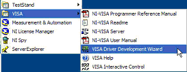
Figure 1 – Windows Location of the VISA Driver Development Wizard
The wizard first prompts you for the device's bus type. Select
PXI/PCI as shown in Figure 2.
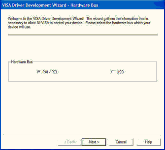
Figure 2 –Hardware Bus Dialog
Device Information
The PCI bus specification requires unique manufacturer and model codes to be embedded into each device. This information is used by the system to identify and communicate with each device. The specification also allows a devices to be identified as part of an integrated subsystem, such as a computer motherboard with video, sound and other peripheral devices. The PCI bus specification accommodates this type of device by providing for two sets of manufacturer and model codes, one for the device, and another for the integrated subsystem.
Under NI-VISA, the manufacturer and model code information is stored in the device .INF file. The wizard prompts you for this information using the dialog illustrated in Figure 3.
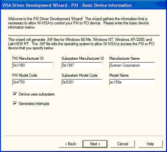
Figure 3 –Basic Device Information Dialog
Here is an overview of the information requested in this window
- PXI Manufacturer ID code – A 16-bit value assigned to the manufacturer by the PCI Special Interest Group (PCI-SIG). The PXI Manufacturer ID (also called the PCI Vendor ID or VID), is located in PCI configuration space at offset 0x0.
- Subsystem Manufacturer ID code – The 16-bit value assigned to the subsystem manufacturer by the PCI Special Interest Group (PCI-SIG). The Subsystem Manufacturer ID, also called the Subsystem Vendor ID (SVID), is optional and when used is located at offset 0x2C.
- Manufacturer Name – The manufacturer name associated with the manufacturer ID code. If Device uses subsystem is selected, Manufacturer Name will be associated with the Subsystem Manufacturer ID , otherwise it will be associated with the PXI Manufacturer ID .
- PXI Model Code – A unique 16-bit value assigned to each device by its manufacturer, it is also called the PCI Device ID (DID). The model code is located in PCI configuration space at offset 0x2
- Subsystem Model Code – A unique 16-bit value assigned to each subsystem by its manufacturer, it is also called a Subsystem ID (SID). The Subsystem Model Code is optional, and present, it is located in PCI configuration space offset 0x2E.
- Model Name– The model name associated with the model code. If Device uses subsystem is selected, the Model Name is associated with the Subsystem Model Code, otherwise it is associated with the PXI Model Code.
The preceding information is available from the device manufacturer and can usually be found in the hardware reference manual. The subsystem manufacturer and model codes are optional and should be left blank if they are not defined. If the manufacturer specifies a subsystem ID, you must enter both ID codes as well as both model codes, and check Device uses subsystem.
- Device uses subsystem – Checking this box indicates that the manufacturer has specified sysbsystem codes for the device.
- Generates interrupts – Checking this box indicates that the device requires interrupt handling support.
Tip: If you are writing an instrument driver, leave Generates interrupts unchecked during the initial stage of development, even if you plan to implement interrupts. It is often helpful to get the basic driver functionality working before attempting to add interrupt support. Interrupt handling can be added to the .INF file by running the VISA Driver Development Wizard again.
If you did not select Generates Interrupts, skip the Interrupt Detection and Interrupt Removal dialog descriptions and continue with the Output Files dialog.
Interrupt Detection
The next dialog (see Figure 5) is the
Interrupt Detection Information window. It allows you to specify the steps that NI-VISA uses when an interrupt occurs to determine whether the current device is the source of the interrupt. If the manufacturer's hardware reference manual does not document the interrupt detection steps, you should be able to derive them from the CSR register descriptions.
Each step usually consists of reading the contents of a device register, and then evaluating the state of certain bits to check the status of an interrupt source on the device. To create a step, click on one of the
Add a step . . . buttons. The wizard will display the
PXI Interrupt Information dialog, as illustrated in Figure 4.
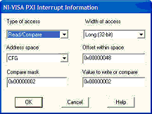
Figure 4 – Interrupt Information Window
In this example, the top four fields specify a step that reads a 32-bit value from CFG space at offset 0x48. The Compare mask value 0x00000002 specifies that bit 1 should be evaluated. After applying the bitwise-AND mask, the resulting value is compared to the Value to write or compare. The hexadecimal value that corresponds to bit 1 being high is 0x00000002. If bit 1 is high, there is a match, which will cause this step to return a logical “true” value to the interrupt detection sequence.
Click OK to add the step to the interrupt detection sequence, which should look similar to Figure 5.
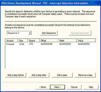
Figure 5 – Interrupt Detection Information Window
More than one step may be required to evaluate whether an interrupt source is generating an interrupt.
A PCI device may have multiple interrupt sources. If this is the case, you should click the Add Sequence button to create an interrupt detection sequence for each interrupt source.
For additional information on detecting PCI interrupts, click the Help button.
Interrupt Removal
The next dialog (see Figure 7) is the
Interrupt Removal Information window, which allows you to specify the steps that NI-VISA will use to suppress an interrupt generated by the device. If the PCI device register programming manual does not document the steps required to remove an interrupt, you should be able to derive them from the CSR register descriptions.
Each step usually consists of writing a value to a device register. As with the interrupt detection sequence, create a step by clicking on one of the
Add a step buttons. The wizard will display the
PXI Interrupt Information dialog, as illustrated in Figure 6.
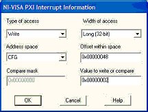
Figure 6 – Interrupt Information Window
This example shows a step that writes the 32-bit value 0x00000002 to CFG space at offset 0x48.
Click OK to add the step to the interrupt removal sequence, which should look similar to Figure 7.
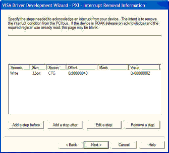
Figure 7 - Interrupt Removal Information Window
More than one step may be required to remove an interrupt.
For additional information on removing PCI interrupts, click the Help button.
Output Files
The last dialog is the Output Files window illustrated in Figure 8. Here, you can specify the PXI instrument file name prefix that will be used for the device, and where the .INF files for each platform should be stored.
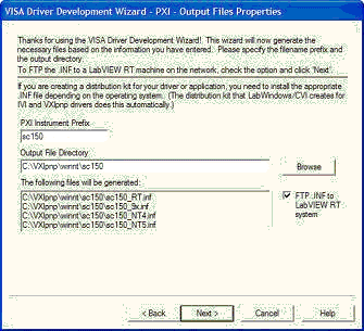
Figure 8 – Output Files Window
Note that LabVIEW Real-Time follows the 8.3 naming convention. Since the wizard appends the string “_RT” to the RT Target INF file name, the unique part of the file name is the first 5 characters.
In some cases, it is useful to have more than one .INF file for using the same device with different configurations. If this is the case, make sure that you provide a distinctive name for each file within the first 5 characters. Using the above example, if you want your files to be named “sc150a.INF” and “sc150b.INF”, you will run into problems because the wizard will truncate both names to “sc150_RT.INF”.
To install the .INF copy it (using anonymous FTP) it to the directory C:\ni-rt\system on the target PXI controller. If you have the LabVIEW Real-Time Module installed, the VISA Driver Development Wizard provides a check box (as shown in Figure 8) to FTP the file automatically. To copy the file to the intended controller using this feature, LabVIEW must be open and the RT system must be selected as the execution target.
The RT Target must be rebooted before the changes take effect.
Viewing the Device in MAX
With the INF file installed, you can view the device using Measurement & Automation Explorer (MAX). Open MAX and press the
<F5> function key to refresh the display.
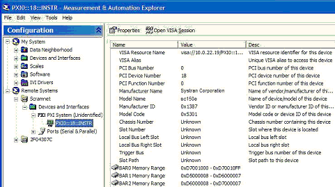
Figure 9. SCRAMNet 150e card as a NI-VISA PXI Device in MAX
Note that the PXI device is now identified as VISA PXI resource. A PXI resource is uniquely identified in the system by three characteristics:
- PCI bus number on which it is located
- PCI device number it is assigned
- Function number of the device