Configuring the Hardware for IEEE 1588
- You will need an NI PXI-668x in each chassis. Install each module according to the instructions in the module’s installation guide:
- Use Ethernet cables to connect the NI PXI-668x in each chassis. The exact network configuration will depend on the number of chassis to be synchronized and the distance between them.
For instance, if you are synchronizing two chassis that are close together, you could directly cable the two chassis together. However if you have 3 or more chassis and/or chassis that are large distances apart, you will need to use a switch. While a standard switch will work with IEEE 1588, it introduces indeterminism into your network, resulting in decreased synchronization performance. NI recommends using a managed Ethernet switch that supports IEEE 1588v2 PTP. You should also make sure that the accuracy specification of the switch meets your synchronization needs. - (LabVIEW RT Controllers Only) Enable the Ethernet adapter on the PXI-668x. To do this, open NI MAX. Under Remote Systems, select your controller, and navigate to the Network Settings tab. Change the adapter mode on the Ethernet adapter of the PXI-668x from Disabled to TCP/IP Network.
Configuring the Software for IEEE 1588 Synchronization
To configure your software for IEEE 1588 synchronization, you can use either NI Measurement & Automation Explorer (MAX) or one of the NI-Sync APIs (LabVIEW or C). The configuration involves two main steps:
- Specify 1588 as the timing source to which you want to discipline your timing board.
- Start participating in the 1588 network and wait for synchronization to be established.
A. Configuring through NI MAX
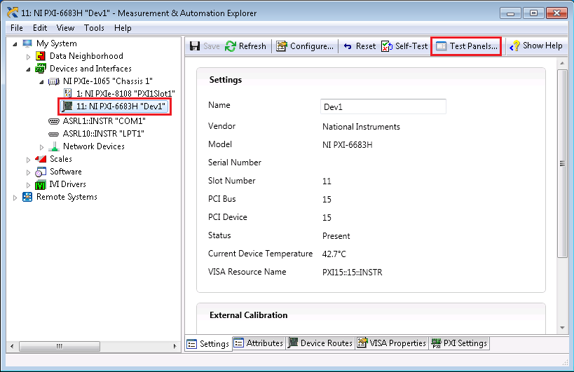
- Open NI MAX and expand out the Devices and Interfaces section. Select the NI PXI-6682(H) or NI PXI-6683(H) in your chassis and select the Test Panels button.
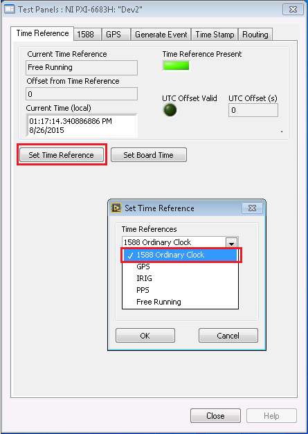
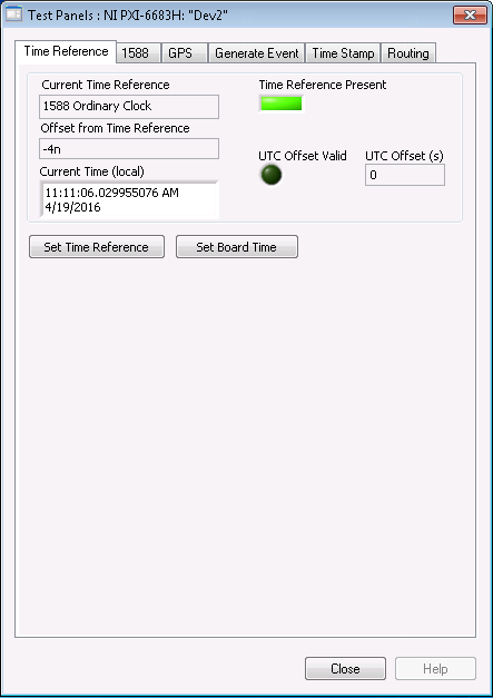
- On the Time Reference tab of the Test Panel, select Set Time Reference. In the dialog box that appears, select 1588 Ordinary Clock as the time reference and then select OK.
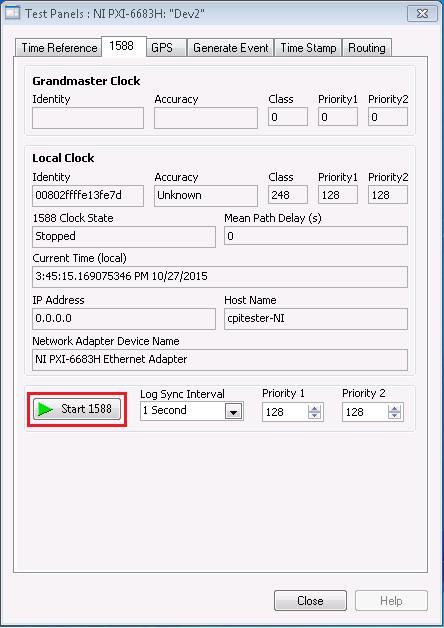
- Navigate to the 1588 tab and select Start 1588. Note that 1588 must be stopped to configure 1588 settings.
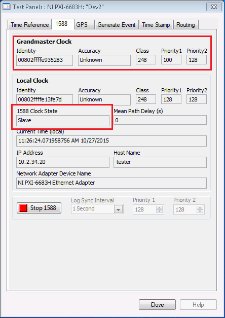
- The 1588 network will then automatically configure the grandmaster and display its details under the Grandmaster Clock section. As 1588 is configuring, you will notice the local clock’s 1588 Clock State property will change from Initializing to Listening and ultimately to either Slave or Master.
- Navigate back to the Time Reference tab. At this point, the Current Time Reference field indicates 1588 Ordinary Clock as the time reference, and the Time Reference Present indicator should be True.
- Repeat the above steps for all PXI(e) systems to be synchronized via 1588.
B. Configuring through LabVIEW
The NI-Sync driver provides LabVIEW example code for configuring 1588 synchronization. You can locate these examples in LabVIEW by navigating to the NI Example Finder, then selecting Hardware Input and Output»Timing and Synchronization»Time-based. The two examples of interest for 1588 synchronization are “Set Time Reference” and “Start 1588 and Wait for Quality”.
“Set Time Reference” Example
This example demonstrates how to specify the timing source to use to discipline your board. Complete the following steps to configure this example for your specific hardware:
- For the Resource Name control, select the alias of your NI PXI-6682(H) or NI PXI-6683(H).
- For the Time Reference control, select 1588 Ordinary Clock.
- Run the VI.
“Start 1588 and Wait for Quality” Example
This example demonstrates how to start participation in 1588, wait for the board clock to stabilize, and then monitor various 1588 properties. Complete the following steps to configure this example for your specific hardware:
- For the Resource Name control, select the alias of your NI PXI-6682(H) or NI PXI-6683(H).
- Toggle the Wait for Quality control to True. NI recommends this configuration because the VI that starts 1588 synchronization does not automatically wait for the 1588 clock to reach a steady state before returning. Enabling the Wait for Quality flag ensures that the application will not continue until the clock has stabilized.
- Specify a timeout. If you enable the Wait for Quality flag, you can specify a timeout to prevent your VI for waiting for quality indefinitely. Once the timeout has been reached, your application will continue regardless of 1588 clock quality.
- Run the VI.
Run both of these examples on all PXI(e) systems to be synchronized via 1588.
(Optional) Configuring IEEE 1588 Synchronization to Be Persistent through Subsequent Reboots
If you configure your time reference settings using NI MAX or LabVIEW as in the previous procedures, the time reference settings will reset upon each reboot of the system and will need to be reconfigured.
To make these settings persistent through subsequent reboots, you can either include the LabVIEW code described in the “Configuring through LabVIEW” section at the beginning of your startup application or complete the following steps in NI MAX:
- Open NI MAX and expand out the Devices and Interfaces section. Select the NI PXI-6682(H) or NI PXI-6683(H) in your chassis and select the Configure button.
- In the Configuration dialog box, navigate to the Time Reference tab and set Time References to 1588 Ordinary Clock.
- Navigate to the 1588 tab and enable Start 1588.
- Select OK.
Synchronizing PXI_Clk10 to the IEEE 1588 Time Reference
At this point, the PXI-668x on each chassis is being synchronized with other IEEE 1588 devices on the network. The next step is to synchronize your chassis’ 10 MHz backplane clock (PXI_Clk10) to this time reference. The method for doing this depends on the hardware you are using. The PXI-6683(H) is capable of single- or multi-device disciplining, whereas the PXI-6682(H) must use multi-device disciplining.
Multi-device disciplining requires the use of a second timing card, such as the PXIe-6674T. Multi-device disciplining also utilizes the more accurate and stable on-board oscillator of the second timing card, resulting in better synchronization performance. For more information on the multi-device architecture, see the PXI Synchronization Module product page. Once you have determined the disciplining method you would like to use, follow the instructions below:
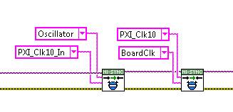
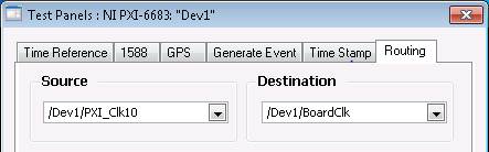
- Single-Board Disciplining with the PXI-6683: If the PXI-6683 is in the system timing slot, you can override the backplane clock of your chassis with the disciplined oscillator of the PXI-6683 by creating the following routes, either in the Routing tab of a MAX test panel or by using the niSync Connect Clock Terminals VI in LabVIEW:
- Source: PXI_Clk10; Destination: BoardClk
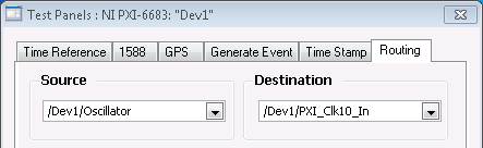
- Source: Oscillator; Destination: PXI_Clk10_In
 Note:
Note: In this example, Dev1 is the alias of the PXI-6683.
- Single-Board Disciplining with the PXI-6683H: Since the PXI-6683H is a hybrid card and does not fit in the timing slot of the chassis, it cannot override the chassis’ backplane directly. Instead, you will need to externally cable the disciplined on-board oscillator of the PXI-6683H to the 10 MHz Ref In connector on the chassis. (Consult your chassis’ user manual to ensure your chassis has a 10 MHz Ref In). To do this, complete the following steps:
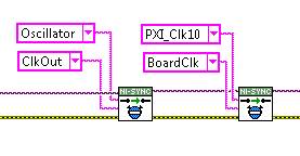
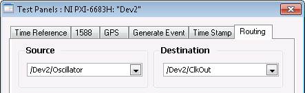
- Either in the Routing tab of a MAX test panel or by using the niSync Connect Clock Terminals VI in LabVIEW, make the following routes:
- Source: Oscillator; Destination: ClkOut
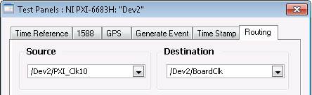
- Source: PXI_Clk10; Destination: BoardClk
- Using an SMB to BNC cable, connect the CLKOUT terminal of the PXI-6683H to the 10 MHz Ref In of the chassis.
 Note:
Note: In this example, Dev2 is the alias of the PXI-6683.
Monitoring IEEE 1588 Performance
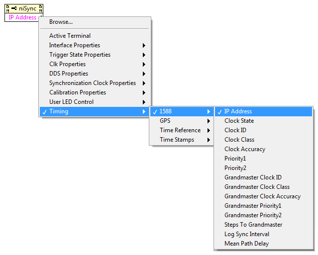
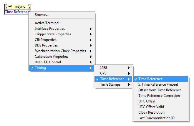
You can use the niSync Property Node (provided with the NI-Sync API) to monitor IEEE 1588 performance in LabVIEW while your application is running. The screenshots below display the 1588 properties available for monitoring, as well as the protocol-independent Time Reference properties available.
For an example of using these properties for monitoring, navigate to
Hardware Input and Output»Timing and Synchronization»Time-based in the LabVIEW Example Finder, and open the “Set Time Reference” example. This VI sets the timing and synchronization module to use a specific time reference specified by the user, and then uses the properties mentioned above to monitor the status of the time reference.
Synchronizing Module Acquisition and Generation
If you followed the above procedures, all chassis in your setup are now sharing the same backplane clock. The last step in setting up a synchronized system is to synchronize the start of acquisition or generation by your individual PXI modules. You can do this by sharing a start trigger. The chassis needs to have the Timing and Sync Upgrade in order to synchronize the backplane clocks.
One option for doing this is to use future time events (FTE). The NI-Sync API provides the ability to generate future time events based on the board time of your PXI-668x. Since the board time of the PXI-668x in each chassis is now synchronized via IEEE 1588, you can use future time events to synchronously generate a trigger on each board at a specific time. These triggers can then be shared with all the modules in each chassis.
For more information on generating a future time event, see the NI-Sync examples in the LabVIEW Example Finder under Hardware Input and Output»Timing and Synchronization»Time-based. The “Generate Event” example there provides the code necessary to generate a future time event.
Once you have generated a Future Time Event, you will still need to program your PXI modules to begin acquisition or generation when they receive the generated trigger. See the “Additional Resources” section below for more information on synchronizing your specific PXI modules.