Network Connection and Configuration
- To use the Real-Time capabilities of your PXI System, you must have LabVIEW and the LabVIEW Real-Time (RT) Module installed, as well as the appropriate drivers for the devices in your PXI system. If you installed the drivers on the host computer prior to installing LabVIEW Real-Time, the Real-Time support would not have installed by default. The driver components for Real-Time can be added by re-running that driver's installer.
- Connect your Real-Time PXI controller to your network using a straight-through Ethernet cable, or directly to your computer using a crossover Ethernet cable.
- Launch Measurement & Automation Explorer (MAX) by selecting Start » Programs » National Instruments » Measurement & Automation.
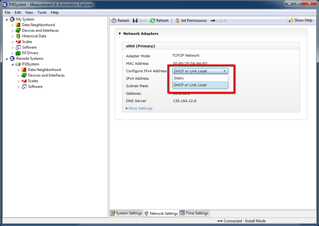
 Figure 1.
 Real-Time PXI Controller Network Settings
- Boot up your PXI System and verify that your PXI System is detected in MAX by expanding the Remote Systems tree (click the arrow beside Remote Systems). PXI Controllers shipped before LabVIEW 8.6 appear with an IP address of 0.0.0.0 by default. PXI Controllers shipped after LabVIEW 8.6 request an IP address from a DHCP server, and choose a unique Link Local IP (169.254.x.x) address if a DHCP provided IP address is not available. If your device is not listed, refresh the list by pressing <F5>.Devices which have not been configured with an IP address must be on the same local subnet as the host in order to configure the IP address. If your device is already configured with an IP address but is not on the local subnet, you may add it to the Remote Systems section by right-clicking on Remote Systems and selecting "Create New". If the controller is not accessible in MAX, the IP address of the system can be viewed by connecting a monitor to the PXI Controller during boot up.
- Select your remote system under Remote Systems and then click the Network Settings tab at the bottom of the window on the right-hand side (see Figure 1).
- If your network uses DHCP, the PXI System should have been assigned an IP address, as DCHP or Link Local is the default configuration option. If not, select the Static option and specify the requested networking parameters. Choose an IP address that is not already in use on the network and click Save on the toolbar. For more information on how to connect a PXI Controller to a development computer via crossover cable, see Using a Crossover Cable to Connect to a LabVIEW Real-Time Target.
- If you wish, within the System Settings tab you can enter a more descriptive name for the remote system, as well as any comments that you would like to include to describe the system and its components. When you are finished, click the Save button on the toolbar to save your changes.
 Figure 2:
 Obtaining IP Address from DHCP Server
Installing Software to your Real-Time System
You must now install the Real-Time software to the controller. This will allow you to run LabVIEW Real-Time applications on the controller. The following steps outline the installation procedure.
- Expand the tree for your PXI system by clicking the arrow beside it.
- Right-click Software and select Add/Remove Software (see Figure 3). A dialog will appear that will allow you to install the appropriate software to your controller (see Figure 4).
 Figure 3:
 Installing Software to the PXI Controller
- Click the "X" next to LabVIEW Real-Time and select Install the feature. Do the same for any other drivers required for your application. Click Next after selecting the desired software. The changes that will be made to the system will then be displayed.
- Verify your selections and click Next to install the software onto the PXI System.
- Click Finish when installation is complete.
 Figure 4:
 Selecting the software components to be installed
Identifying your PXI Hardware
You must now identify the PXI Controller and the PXI Chassis. The following steps outline this procedure.
- Expand the Devices and Interfaces tree under your PXI System by clicking the arrow beside it.
- Right-click the PXI System now listed under Devices and Interfaces and select Identify As (see Figure 5).
- Select the controller that matches the controller installed in your system.
 Figure 5:
 Identifying the PXI Controller
- Now, identify the PXI Chassis as well. Right click the Chassis listed under PXI System and select Identify As (see Figure 6).
- Select the chassis that matches the chassis in your system.
- You are now ready to use your Real-Time PXI system!
 Figure 6:
 Identifying the PXI Chassis