- Selecting File»New VI to open a blank VI.
- Place a Formula Node on the block diagram.
- Right-click on the diagram and navigate to Programming»Structures»Formula Node.
- Left-click to select the Formula Node.
- Place the Formula Node on the block diagram by left-clicking, dragging, and releasing the mouse.
- Right-click the border of the Formula Node and select Add Input from the shortcut menu.
- Label the input variable x.
- Repeat steps 3 and 4 to add another input and label it y.
- Right-click the border of the Formula Node and select Add Output from the shortcut menu.
- Label the output z1.
- Repeat step 5 to create another output, and label this output z2.
Note: It is considered good programming practice to keep the inputs on the left border and the outputs on the right border of the Formula Node. This helps you follow the data flow in your VI and keep your code organized.
- Enter the expressions below in the Formula Node.
- Make sure that you complete each command with a semicolon. Notice, however, that the if-statement does not require a semicolon on the first line.
if (x*y>0)
z1 = 3*x**2 - 2*y**3;
else z1 = 0;
z2 = sinh(z1);
- Create controls and indicators for the inputs and outputs.
- Right-click on each input and select Create»Control from the shortcut menu.
- Right-click on each output and select Create»Indicator from the shortcut menu.
Note that you can change the control and indicator names to their respective variable by editing their labels.
- Place a While Loop around the Formula Node and the controls.
- Right-click on the diagram and navigate to Programming»Structures»While Loop.
- Left-click to select the While Loop.
- Place the While Loop on the block diagram by left-clicking, dragging, and releasing the mouse.
- Right-click the Stop icon and Create Control. Label it as Stop.
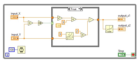
- Add a Wait (ms) function inside of the While Loop to conserve memory usage, and wire in 100 milliseconds as a wait time. Your block diagram should appear as follows:
- Click the Run button to run the VI. Change the values of the input controls to see how the outputs change.
In this case, the Formula Node helps minimize the space required on the block diagram. Accomplishing the same task without the use of a Formula Node requires the following code: