Assumptions
Due to the amount of knowledge required to fully understand digital systems, this tutorial assumes you are familiar with the following concepts: Digital Signals, Impedance Matching, Transmission Lines, Termination of Digital Signals, and Oscilloscopes. Also, all interconnections (cabling) are assumed to have a 50 ohm characteristic impedance.
Basics of Measuring Signal Integrity in a Digital System
To introduce the concept of measuring signal integrity in a digital system, we will evaluate a basic measurement of a digital signal taken as if the scope is a part of the system. This means that the output of a digital line is connected directly to a scope through an accessory:

Figure 1: Oscilloscope in series with a digital output from a digital instrument. The two instruments are connected using a VHDCI to SMB connector block. This common scenario can be used to verify signal integrity at the output of the accessory terminals.
Here, the scope is at the end of the transmission line, which means the signal is terminated at the scope. 1 Mohm termination at the scope means you will fully reflect a square wave signal back to the transmitter. With 50 ohm termination, all reflections are removed while reducing the voltage sensed by the scope in half. This reduction is due to the 50 ohm voltage divider circuit created when the AC signal travels through the 50 ohm characteristic impedance of the cable to the 50 ohm source impedance at the transmitter.
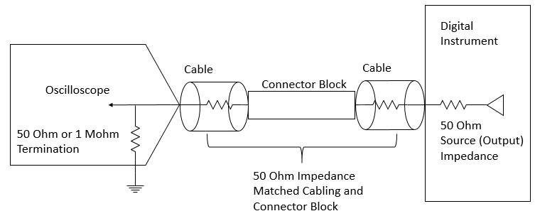
Figure 2: Schematic representation of Figure 1 setup.
The resulting measurement will show you the digital signal at the end of the transmission line exactly how a Unit Under Test (DUT) would see it.
Various Probing Application Scenarios
Measuring Digital Signal Integrity with an Oscilloscope Connected in Parallel
A more difficult scenario exists when attempting to measure digital signal integrity when the scope is not terminating the signal into itself. This is where you have your digital instrument generating a square wave to a device under test, and you want to connect the scope probe in parallel with the data transmission in order to view the signal as it propagates through the transmission line medium:
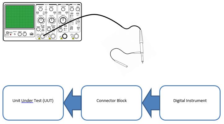
Figure 3: Oscilloscope probe measurement representation on a system. The probe is to be connected in parallel to view the digital system as it travels through the transmission line.
There are two main factors to consider when measuring a digital signal in this scenario: the effect and placement of your hand probe on the circuit.
When you use the probe to measure a digital signal in a parallel configuration, the input impedance, capacitance, and inductance the probe adds to the circuit should be carefully analyzed and understood. For example, a passive probe with a large amount of input capacitance can cause your signal to look distorted by filtering out higher frequency components in your signal (rounding edges, slowing down edge transitions). You may consider using an active probe if the effect of the probe causes substantial capacitance and distortion on your signal. Additionally, the ground wire can add inductance to the circuit which could also result in a slower edge transition on the signal. The ideal ground wire is short and should be connected as close to where the signal is probed as possible to minimize any inductance loop created.
When determining where to probe your digital signal in this setup, there are a few key fundamentals to understanding how to acquire the best results and how your setup must change based on the probe position in the transmission line:
- Probing at the beginning of the transmission line (where the signal comes out of the transmitter at the digital instrument) will not give you an accurate representation of the signal received at the DUT. You will see a “stepped” digital signal on your oscilloscope based on the transmitted and reflected signal through the transmission line.
- Probing in the middle of the transmission line (where the connector block connects the digital instrument and the DUT) will also show a similar, but less dramatic stepped digital signal. The reason is the same: you see the signal passing through and some later time you see the reflected wave come back to the digital instrument. Since the propagation time from the connector block to the DUT and back to the connector block is shorter than the round trip delay at the digital instrument, the step is less pronounced.
- The best location to probe is at the end of the transmission line, as close to the receiver as physically possible. This signal will be the closest representation to the digital wave your DUT is actually receiving.
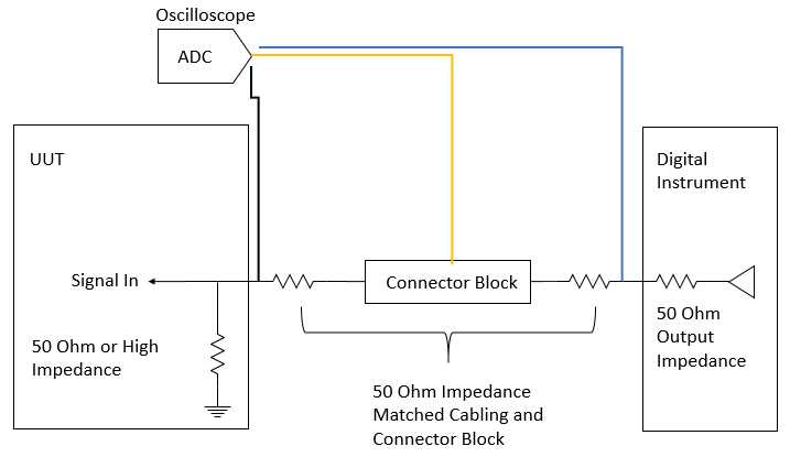 Figure 4
: Schematic representation of Figure 3. Note that the black, yellow, and blue lines are possible probe points. The resulting measured digital rising edge you would expect to see on a scope is shown in Figure 5.
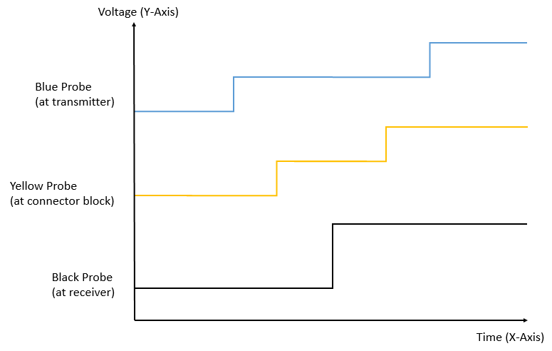 Figure 5
: Oscilloscope measurements of a digital rising edge at various probe points in the transmission line. The wave begins at the transmitter (shown by first half step on blue probe) and propagates down the transmission line, seen by the yellow probe. The wave reflects at the receiver (black probe) which doubles the amplitude of the signal as it reflects back to the transmitter . The reflected energy is monitored at the yellow probe and finally the blue probe where the 50 ohm output impedance dissipates the reflected energy.
Note: The above Figure 5 assumes a high impedance probe with the scope terminated with high impedance. Changing the termination to 50 ohm while using a bare 50 ohm cable will result in no reflections.
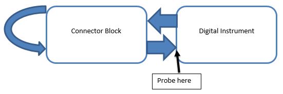
Measuring Digital Signal Integrity for Loopback Testing
An important change in the setup when you are performing a loopback test is that the path is now twice as long as the previous example. This is because the signal is travelling both to the DUT or Connector block and then terminates where it originated. It is important to note the end of the transmission line is now at the digital instrument, and that is where you would need to probe to get an accurate picture of the digital signal at the receiver.
For NI digital instruments, this would require removing the outer shell of the VHDCI connector and probing directly to the wire. In many cases, this should not be necessary for your application. However, if it is necessary, it is important to measure at the right location to show the actual received digital signal correctly.
Measuring Digital Signal Logic Using a Digital Instrument
There are applications where you want to analyze the logic of a digital signal rather than the analog voltage levels required for signal integrity testing. For these applications, using a digital instrument to probe the line or bus allows the user to analyze the digital logic patterns. An example of this type of analyzing is connecting a flying lead cable to a high impedance digital input in parallel with another digital bus. Doing so may cause the cable to load the line and cause reflections. The NI solution to this issue is to use a 1 kOhm barrel attenuator that attaches to the front of the flying lead cable which reduces the loading effect the probing cable has on the system. For more information about this setup, please visit the Digital Flying Lead Cable User Guide on ni.com and reference the section Attenuated Acquisition.