Measure Real Power with a Digital Multimeter

Updated Dec 18, 2023

Environment

Hardware

  • Digital Multimeter Device

When prototyping or testing a device, engineers often want to measure the amount of power the device consumes. Especially considering trends in consumer electronics, understanding power consumption enables engineers to optimize circuit designs for size, heat transfer, and critical functionality.
 

A power measurement application requires one measurement device to capture the voltage across the terminals of a load, and the second device to capture the current going through the load. However, the actual power calculation depends on the resistive and reactive components (capacitors and/or inductors) in the circuit. The power dissipation in a purely resistive circuit is always a function of the voltage drop and current draw through the circuit.

Reactive circuits appear to function like resistive circuits because they produce voltage drops and draw current. However, reactive circuits actually store or return power. The reactive components (e.g. capacitors, inductors) cause a phase shift up to 90 degrees between the voltage and current waveforms which reduces the overlap between the two curves and effectively decreases the power delivered to the loads. This phenomenon is represented by three different power measurements: reactive power, apparent power, and real power. These three power measurements have a phase relationship that can be visualized in the power triangle, shown below.
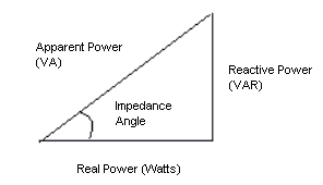
 

Figure 1: Power Triangle

Real Power

Real power is the measure of a circuit’s dissipative elements (R) and is represented by a P, which has a unit measure of Watts (W). There are actually two different techniques that are used to measure real power. The first way is to take the time average of the instantaneous product of voltage and current. Another common method is to use the impedance angle depicted in the power triangle above. The cosine of the impedance angle is directly proportional to the amount of reactance in a circuit, which is called power factor (PF). Hence, you can also calculate real power by using the following formula:

Power Factor (PF)= cos (Impedance phase angle) OR Real Power / Apparent Power

Real Power (P) = [V * I * PF] OR (V * I)

A PF of 1 represents a purely resistive load and power factor less than 1 represents a reactive circuit. Figure 2, shows an example of a real power measurement on a purely resistive circuit.

Figure 2: Real Power in a purely Resistive Circuit


To accurately measure real power, you need the following capabilities:

  • Voltage and current waveform acquisition capability
  • Simultaneous acquisition of both measurement waveforms
  • Both measurement devices must acquire simultaneously
  • Analysis functions

Traditionally, this measurement functionality was only found in specialized power meters because a traditional digital multimeter has asynchronous clocks and doesn’t provide synchronized waveform acquisition capabilities. However, using the modern digital multimeter architecture of the NI PXIe-4080 FlexDMM, which includes a 1.8 MS/s digitizer capability, along with NI LabVIEW analysis functions, you can build a true power measurement system, as shown in Figure 3. The system requires two PXIe-4080 FlexDMMs: one configured to measure voltage and the other to measure current. Using the NI-DMM instrument driver, you can configure two FlexDMMs to trigger off the same PXI trigger line. The block diagram below is an example of how you would make these measurements in LabVIEW.
 

Figure 3: LabVIEW Analysis VIs Used to Calculate True Power


The following graphic provides a more holistic application architecture capable of scaling with changing test requirements.


Figure 4: Real power test application architecture
 

For more information about the components in the above architecture, please refer to the following links: