Hardware Setup
Performing output short circuit current tests using this PXI system are require two main connections. The PXIe-414x SMU must be connected to VDD and VSS, and the PXI-2535 matrix switch can be used to connect the SMU to digital output pins, or the PXIe-6556's PPMU capabilities can be used directly for the digital pins.
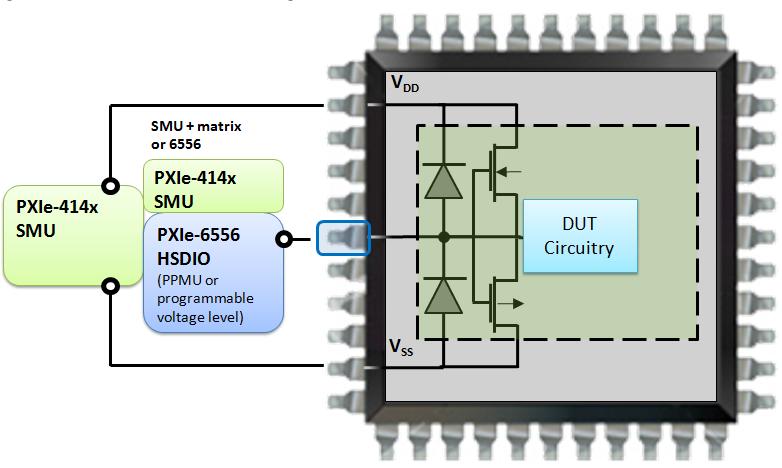
Figure 1: Test setup for output short circuit current
To perform an output short circuit test (IOS) in the logic-high state, the device pin must first be preconditioned to be a logic-high, then the SMU or PMU must be set to apply a voltage of 0 V, simulating a short circuit from the pin to ground. This will result in a large amount of current flow from the output pin, stressing the output circuitry.

Figure 2: Output short circuit test for logic high
Two strategies can be implemented to ensure device safety:
- Only allow the short circuit to last for a certain amount of time (usually a few milliseconds) to prevent damage from overheating
- Limit the output current that the SMU draws to a value below the DUT's heat specification
One or both of these methods can be used during testing. In this example, the current is limited (for example 20 mA) to ensure that the device does not overheat regardless of the time duration of the short circuit. To yield a pass/fail result, the current output from each pin is measured by the SMU or PMU. Under short circuit conditions, each of the pins should hit the current limit of 20 mA if they are working properly. Defective pins, on the other hand, would not be able to provide this much current, therefore a pass/fail threshold of 18 mA can be used to gauge the health of each pin’s output circuitry.
Testing for IOS in the logic-low state is very similar, except that the output pin is set to 0 V (or VSS) and the SMU or PMU is set to 3.3 V simulating a short circuit between the output pin and VDD. In this case, the SMU or PMU is the source and the chip must dissipate the current. Again, current limiting or time limiting can be employed to protect the device. In this example, a threshold of 18 mA is used to gauge the health of these pins by making sure they can dissipate a certain amount of current.

Figure 3: Output short circuit test for logic low
Automated Test Steps
- Power the DUT by applying VDD
To power the DUT, the PXIe-4141 SMU should be configured to output the rated voltage of the device (usually 3.3 V). Setting a current limit is highly recommended to prevent damage to the DUT.
- Condition the DUT outputs to logic-high states
The next step is to make sure that any bidirectional pins are set to be outputs. For an IOS high test, all outputs must be set to the logic-high state, for an IOS low test, all outputs must be set to the logic-low state. Interfacing with and conditioning a DUT can be done through a variety of different hardware options, but the PXIe-6556 was chosen for its PPMU capabilities allowing one device to be used for DUT control as well as for DC parametric tests.
- Switch to the channel to be tested
For automated setups, a switching system must be utilized to gain the most speed and repeatability. Like the other tests shown in this reference architecture, the same PXI-2535 high-density matrix switch can be employed to allow the PXIe-4141 SMU to communicate to all the pins under test. At this point, since all pins have been conditioned to the logic-high state and the SMU and HSDIO is already configured, the matrix simply needs to connect the PXI hardware to the pin under test and measurements are ready to be made.
- Measure the current
Once the SMU is configured, the device is conditioned, and the pin-under test is connected, measuring the current using the SMU will yield a measure of the health of a pin. For an IOS high test, the current will flow into the SMU and should be at least an expected negative amount (in this example the threshold is -18 mA, where the hardware limit is set to 20 mA). For an IOS low test, the current will flow out of the and the current should be at least a certain positive amount (in this example the threshold is 18 mA, where the hardware limit is set to 20 mA).
If the pin can source or sink enough current, then it is deemed to be passing.
- Switch to the next channel and repeat.
Repeat steps 3 and 4 for each output pin on the device under test, combining all results into an array for easy display and analysis.
Software Setup
The software for this Output Short Circuit Test is developed using NI LabVIEW and NI Switch Executive. LabVIEW is used as the primary Application Development Environment (ADE) while Switch Executive is used to configure routes on the high-density matrix. For simplicity, only the Output Short Circuit High (IOSH) test is incorporated into the code. To include the IOSL test, add steps to the code as per the description above.
The following software versions were used to implement the Opens and Shorts Semiconductor Test:
The LabVIEW code described in this document can be downloaded from the link at the bottom of this document.
Note: Functional blocks in the LabVIEW graphical programming language are known as ‘Virtual Instruments’ or ‘VIs’. The acronym ‘VI’ will therefore be used when describing procedures in this section.
The following steps use the PXI-2535 to connect PXIe-414x channels to the pins to be tested.
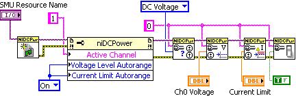
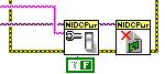
- Initialize the SMU based on the resource name and set the voltage level and current limit autorange features on the device to 'On'. Next, Set the utility channel on the SMU to power your device by changing the voltage setpoint. Set the current limit to the max allowable current in order to protect your device and test setup.
-
If necessary, add digital I/O code here to condition your DUT to the appropriate logic state such that all pins to be tested are configured as outputs in the logic-high state.
-
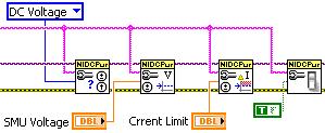
Next, set the PXIe-4141 to 0 V. This SMU channel will be switched to each pin in the output-high state effectively shorting each output pin under test.
-
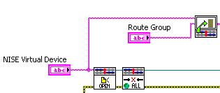
Initialize a session to the matrix switch via NI Switch Executive. The NI Switch Executive (NISE) Virtual Device Name is input to the Open Session VI to begin communication with all the switches in the system. The individual routes to each pin on the device under test are retrieved from the route group specified, and used later to make the connections. The "extract_routes" subVI can be found at the bottom of this page.
-
For each pin on the device under test (as specified by each route in the route group), make a connection to the pin and then perform a current measurement on the PXIe-4141 to measure the current flow through the CMOS transistors on each pin. Once this measurement has been taken, disconnect from the pin and repeat the process on the next.

-
Show a histogram of the pin measurements and display the individual values in a table.

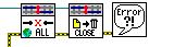
- Power down and close SMU session.
- Disconnect all switch channels and close switch session.
The front panel of the attached example code allows the user to control the settings of the SMU, Switch and HSDIO instrument. It displays results of the IOS test using a text array as well a histogram.
