1. Designate a computer on your Local Area Network (LAN) as the server. This is the computer that is connected to the hardware and therefore runs a server process that handles all communication with the hardware. A Lookout Development package, as well as purchased client connection license, must be installed on the server computer for this tutorial. Also, designate at least one or more separate computers on your LAN as clients. The client systems need only a Lookout Client installation, which is provided at no cost because the server’s client connection licenses will control the connections.
2. Launch the Server example program attached to this document.
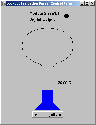
3. Examine the server process. The process has a potentiometer, Pot1, that can be moved to simulate the level in a tank. A server process usually does not have any user interface. It's the client that will contain a Pot on the panel that the operator can manipulate. To simulate actual hardware, a ModbusSlave object is used in this example as the driver object. The advantage of the ModbusSlave object is that no hardware is actually required, so the example can be used by everyone. Pot1 is connected to ModbusSlave1.40001, so the 40001 registers of the ModbusSlave driver object is holding the tank level information. Also, under
Edit Data Member Configuration of the ModbusSlave1 object, note that the TankLevel alias data member scales the 40001 registers from 0 - 100 to 0 - 250,000 gallons.

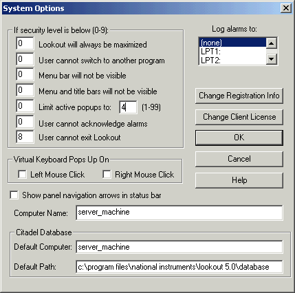
4. Examine your server computer name by selecting
Options»System. In this tutorial, the server computer’s name is server_machine.

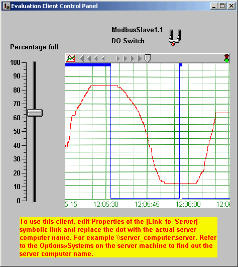
5. While still on the server computer, open the Client process from the attached file. The Client process should open and work fine on the same machine. Notice that the [Link_to_Server] Symbolic Link points to \\.\server (=process with a server as the name, running on the same computer).

6. You can now move the Percentage full control and flip the DO Switch in the client process, and the changes will be reflected in the server process. Also, note that you will receive high and low-level alarms.
7. Now that the server and client processes are both working on the server machine, copy the modified client process to the client computer, and open the client process. The client process should open with red Xs, since the URL connections to the server need to be corrected with the actual name of your server computer. You will need to replace the dot in the symbolic link URL with the actual name of your server computer (\\server_machine\server in this tutorial). When you make this correction, the red Xs will disappear, and the HyperTrend object will begin drawing the graph.
8. Even after completing step #7, you may still be noticing problems with the HyperTrend display. This may be due to a time-synchronization problem between the server and client computers. Select
Options»Time Synchronization»Add, and select the server computer for time synchronization.
9. Now, all controls should work properly, but notice that if you set either full level or no level, the client machine is not receiving any alarms. To register the alarms from the server to appear on the client, select
Alarms»Select Processes and use the
Add button to add the server process, running on the server computer, to selected processes.