Why convert Excel worksheets into a NISE configuration?
Excel worksheets offer a familiar format in which to define your switching system. By converting Excel worksheets to Switch Executive, you can quickly construct a complex switch configuration using an Excel template. The template may contain data that is new or sourced from your existing Excel files. After converting, you can manage the switch configuration like any other configuration within Switch Executive.
By converting Excel to Switch Executive, you can:
- Define your switching system in a familiar spreadsheet format.
- Move your switch definitions into an environment designed for switch management—one that integrates multiple modules and automatic routing.
- Use your switch definitions with other applications.
- Leverage Switch Executive’s Measurement and Automation Explorer (MAX) interface and configuration API to further customize the converted definitions.
In order to ensure that the migration is a success, use the following best practices:
- Use the suggested Excel template - SwitchExecutiveTemplate.xls
- Run the conversion program - ConvertExceltoNISE.xls
- Validate the configuration
- Test the configuration using the Switch Executive Test Panel
Use the Suggested Excel Template, SwitchExecutiveTemplate.xls
Consider the migration of Excel to NISE as a step-by-step process:
Open the template in Excel and define the Virtual Device name.
Select the Devices worksheet and type in the Virtual Device Name - the name of the virtual device that will be created in Switch Executive.

Define IVI devices.
Select the devices worksheet and fill in a row of data for the IVI device you wish to add to the Switch Executive virtual device.
- IVI Logical Name - a user-defined name used by IVI to point to a virtual instrument and allow for interchangeability. You use the logical name to access an IVI device. If you are adding a preconfigured IVI device to the Switch Executive configuration, then use its logical name as shown in MAX. Otherwise, choose a new name here to create a new IVI logical name for the instrument.
- IVI Software Module - a vendor-specify module containing the commands and functions necessary to communicate with the instrument. You may find the list of valid software modules for your system within MAX.
- IVI Driver Setup - a driver-specific string containing setup flags for configuring the instrument. You may find the list of valid driver setup string flags in the Options String parameter in your driver's help file.
- Resource Name - the name of the instrument in the system. This name is either the NI-VISA alias or the NI-DAQmx device name set in MAX. This attribute is optional for some drivers and may be undefined by specifying the empty string. For the sampleSwitch driver, it is an empty string.
- Comment - a comment string stored in the Switch Executive configuration for the added device. This attribute is optional and may be undefined by specifying the empty string.

Repeat these steps for each IVI device you wish to add.
Define channels and channel exclusions.
Select the channels worksheet and fill in a row of data for each channel you wish to override (define attribute values other than the defaults) in the Switch Executive virtual device.
- Alias Name - a nickname for a channel in Switch Executive defined by the user to model the system. This attribute is optional and may be undefined by specifying the empty string.
- IVI Logical/Channel Name - a concatenation of the IVI Device and IVI Channel Name of the channel.
- R4R - an attribute that marks the channel as reserved for routing. Channels marked as reserved for routing are used by Switch Executive to complete routes within a switch. This attribute is optional and may be undefined by specifying the empty string.

or

- Disabled - an attribute that marks the channel as disabled. Channels marked as disabled are not used in connections/routes. Disabling a channel can be useful for making unused channels or channels with a damaged relay inactive. This attribute is optional and may be undefined by specifying the empty string.

or

- Comment - a comment string stored in the Switch Executive configuration for the channel. This attribute is optional and may be undefined by specifying the empty string.

Repeat these steps for each channel to override its defaults. Next, select the Exclusions worksheet and fill in a row of data for each channel exclusion you wish to add to the Switch Executive virtual device.
Definition: A channel exclusion is a connection rule used to prevent specific channels from connecting to one another. Exclusions are predominately used for safety purposes.
- Exclusion Name - the name for the exclusion.
- Exclusion Type - the type of the exclusion, Mutual or Set. A mutual exclusion is a list of channels that should never connect to one another. A set exclusion is two lists of channels where channels from the first list should never connect to channels of the second list.

or

- Set1 or Mutual Channels - the list of channels (given by Logical Name) for the Set1 or mutual channels of the exclusion. Please each channel on its own row.

- Set2 Channels - the list of channels (given by Logical Name) for the Set2 channels of the set exclusion. Note: this column is left blank for Mutual exclusions. Again, place each channel on its own row.
For a Mutual Exclusion:

For a Set Exclusion:

- Comment - a comment string stored in the Switch Executive configuration for the channel exclusion. This attribute is optional and may be undefined by specifying the empty string.

Repeat each step for each channel exclusion you wish to add.
Define hardwires and buses.
Select the Hardwires worksheet and fill in a row of data for each hardwire you wish to add to the Switch Executive virtual device.
Definition: A hardwire is any physical connection between switch channels such as wiring, analog buses, matrix expansion plugs, etc. A hardwire can have any number of channels attached to it.
- Hardwire Name - the name for the hardwire.
- Channels on Hardwire - the list of channels (given by Logical Name) for the hardwire. Place each channel on its own row.
- Comment - a comment string stored in the Switch Executive configuration for the hardwire. This attribute is optional and may be undefined by specifying the empty string.

Repeat each step for each hardwire you wish to add. Next, select the Buses worksheet and fill in a row of data for each bus you wish to add to the Switch Executive virtual device.
Definition: A bus is a collection of hardwires spanned across adjacent channels on devices. Create a bus to quickly create a group of hardwires and associate them with a single named object. Buses are particularly helpful when hardwires are used for column or row expansion in a matrix where a series of channels are connected to another series of channels.
- Bus Name - the name for the bus.
- Hw Start Index - an integer used to name the hardwires created for the bus. The hardwire names are named by appending increments of the Hw Start Index to the bus name.
- Attached IVI Device - the list of devices (given by Logical Name) attached to the bus. Place each device on its own row.
- Base Channel - the Logical Name of the channel from which to start spanning the bus.
- End Channel - the Logical Name of the channel to end spanning the bus.
- Comment - a comment string stored in the Switch Executive configuration for the bus. This attribute is optional and may be undefined by specifying the empty string.

Repeat each step for each bus you wish to add.
Define route groups and routes.
Select the Route Groups worksheet and fill in a row of data for each route group you wish to add to the Switch Executive virtual device.
Definition: A route group allows you to group individual routes (and/or other route groups) and associate them with a single named object. Use a route group to set up simultaneous switching configurations quickly. A route group also enables NI Switch Executive to make better decisions about which resources to use when creating a route. When two or more routes are added to a route group, NI Switch Executive ensures these routes do not use conflicting resources.
- Route Group Name - the name for the route group.
- Child Route Groups - the list of names of route groups that are a part of this route group. Place each route group name on its own row. This attribute is optional and may be undefined by specifying the empty string.
- Child Routes - the list of names of routes that are a part of this route group. Place each route name on its own row. This attribute is optional and may be undefined by specifying the empty string.
- Comment - a comment string stored in the Switch Executive configuration for the route group. This attribute is optional and may be undefined by specifying the empty string.

Repeat each step for each route group you wish to add. Next, select the Routes worksheet and fill in a row of data for each route you wish to add to the Switch Executive virtual device
Definition: A route is a user-defined connection from one channel (row, column, COM, NO, etc.) to another.
- Route Name - the name for the route.
- Route - a fully specified path enclosed in square brackets consisting of one or more endpoint channels delimited by ->.

- Comment - a comment string stored in the Switch Executive configuration for the route. This attribute is optional and may be undefined by specifying the empty string.
Repeat each step for each route you wish to add. Save the workbook.
Run the Conversion Program, Convert Excel to NISE.xls
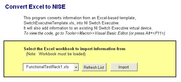
Open the Convert Excel to NISE.xls example program in Microsoft Excel. Select the template workbook that you completed in the previous step. Import the workbook.

Validate the Configuration
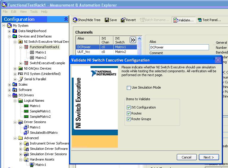
Open Measurement and Automation Explorer (MAX) and select the configuration. Run the "Validate" command on the virtual device.

Validating the virtual device confirms that all the driver software, routes, route groups, and hardwires/buses are acceptable in their current configuration.
Test the Configuration Using the Switch Executive Test Panel
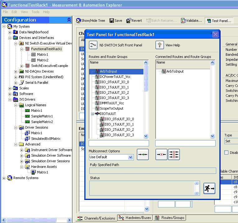
Open the test panel in the virtual device. Connect a route or route group to test the virtual device.

By connecting a route, you are demonstrating that the virtual device is controlling your system the way it is intended. For NI switch hardware, you can also open the NI-Switch Soft Front Panel to verify the routes in a graphical display of the hardware.