The following terminal types correspond with RTD measurements:
- RTD x (+/-): Most NI RTD hardware refers to RTD x+ and RTD x- terminals for each differential measurement channel, where x refers to the channel number.
- AI x (+/-): Some devices may refer to AIx+ and AIx- instead.
Connecting the RTD to Your Device
The next step is to physically connect the RTD to your DAQ device.
2-Wire RTD Signal Connection
Connect the red RTD lead to the excitation positive. Place a jumper from the excitation positive pin to the channel positive on the DAQ device. Connect the black (or white) RTD lead to the excitation negative. Place a jumper from the excitation negative to the channel negative on the DAQ device.
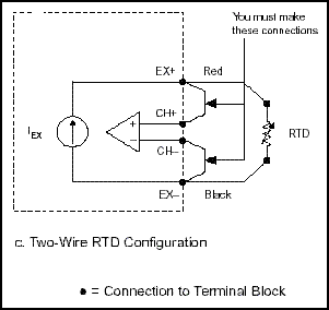
Figure 2. 2-Wire RTD Measurement
In the 2-wire method, the two wires that provide the RTD with its excitation current and the two wires across which the RTD voltage is measured are the same.
The easiest way to take a temperature reading with an RTD is using the 2-wire method; however, the disadvantage of this method is that if the lead resistance in the wires is high, the voltage measured, VO, is significantly higher than the voltage that is present across the RTD itself. The NI 9217 analog input module does not support 2-wire measurement configurations.
3-Wire RTD Signal Connection
Connect the red RTD lead to the excitation positive. Place a jumper from the excitation positive pin to the channel positive on the DAQ device (Note: This step is not necessary with the NI 9217; it internally connects these two channels, see Figure 3). Connect one of the black (or white) RTD leads to excitation negative and the other to channel negative.
Figure 3 shows the external connections for the measurement as well as the pinouts for the NI 9217 RTD module. The excitation positive is connected to RTD0+ because the NI 9217 internally connects this to the excitation terminal.
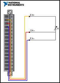
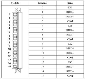
Figure 3. 3-Wire RTD Measurement
4-Wire RTD Signal Connection
To connect this RTD, simply connect each of the red leads on the positive side of the resistive element to the excitation positive and channel positive on the DAQ device. Connect the black (or white) leads on the negative side of the resistive element to the excitation and channel negative on the DAQ device. The two additional leads from a 2-wire RTD increase the attainable accuracy. Figure 4 shows the external connections for the measurement as well as the pinouts for the NI 9217 RTD module.
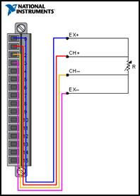
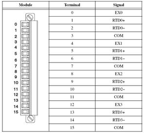
Figure 4. 4-Wire RTD Measurement
The 4-wire method has the advantage of not being affected by the lead resistances because they are on a high-impedance path going through the device that is performing the voltage measurement; therefore, you get a much more accurate measurement of the voltage across the RTD.
NI MAX Configuration
You can use NI MAX to quickly verify the accuracy of your measurement system setup. Using an NI-DAQmx Global Virtual Channel, you can configure an RTD measurement without any programming. A virtual channel is a concept of the NI-DAQmx driver architecture used to represent a collection of device property settings that can include a name, a physical channel, input terminal connections, the type of measurement or generation, and scaling information.
Follow these steps to begin:
- Configure your RTD Virtual Channel for your hardware on the NI-DAQmx Global Channel tab, specifying the RTD type as 2-wire, 3-wire, or 4-wire.
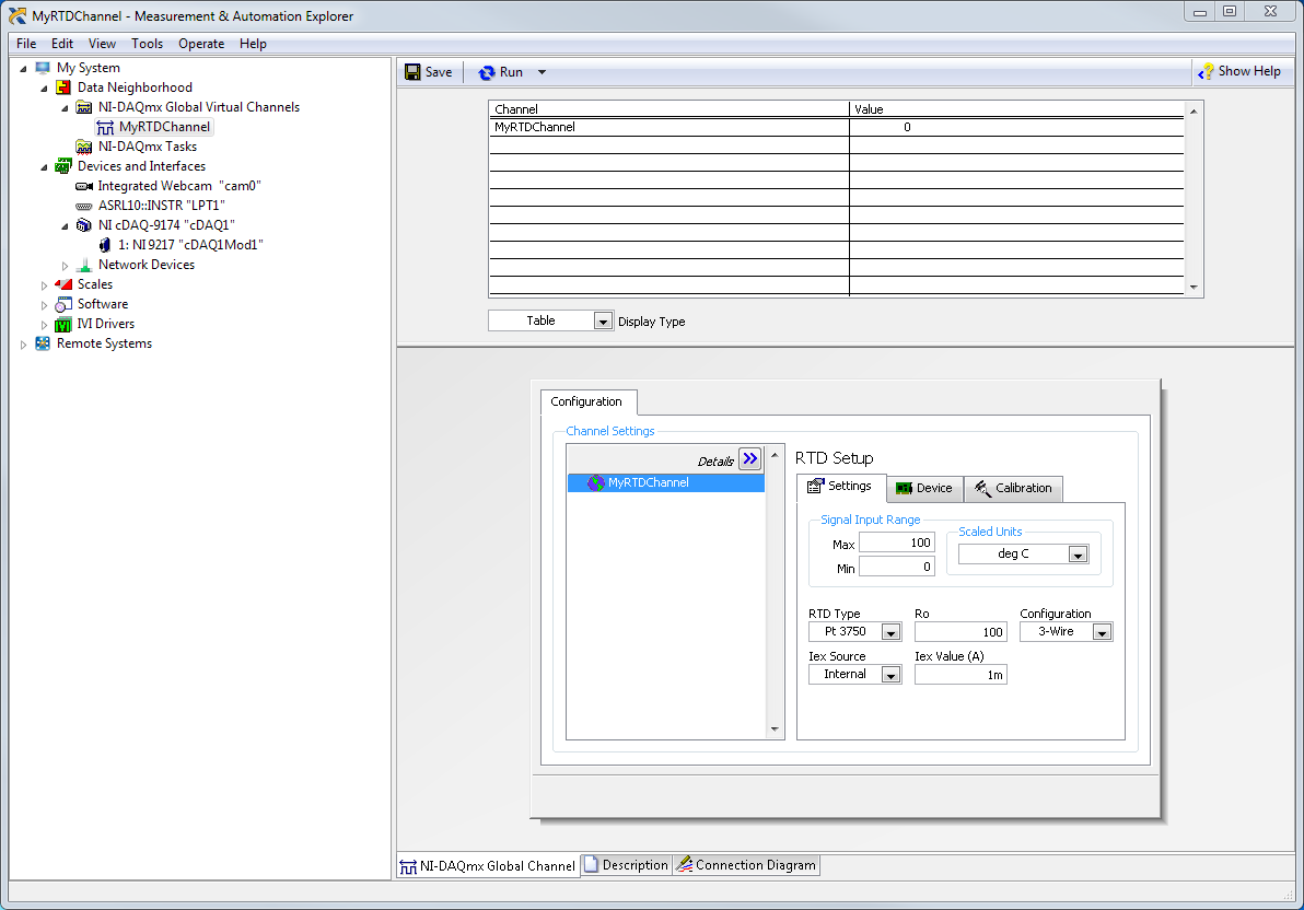 Figure 5
. RTD Configuration in Global Channel
- Click the Connection Diagram tab in NI MAX to continue.
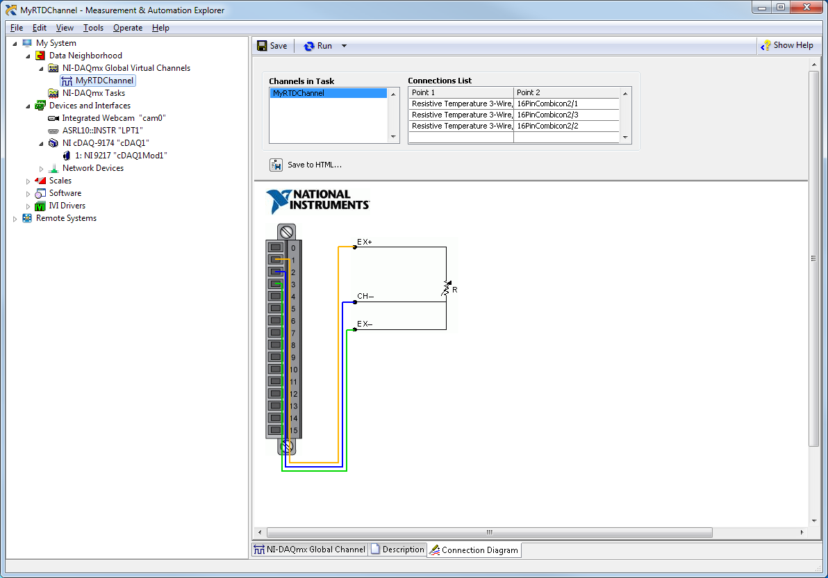 Figure 6
. RTD Connection Diagram
Configuring an RTD Measurement
Once the sensor is connected to the measurement device, continue with configuration as follows:
- With NI MAX open, select Data Neighborhood and click Create New.
- Select NI-DAQmx Global Virtual Channel and click Next.
- Select Acquire Signals»Analog Input»Temperature»RTD.
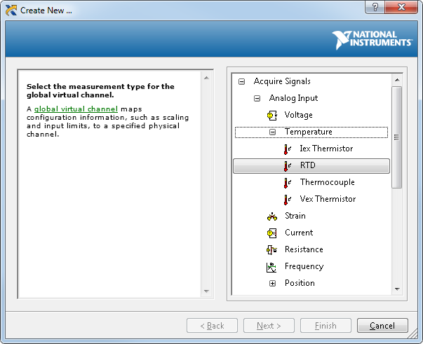 Figure 7
. Creating an NI-DAQmx Virtual Channel
- Select ai0 or whichever physical channel you intend to connect your RTD. A physical channel is a terminal or pin at which you can measure or generate an analog or digital signal. A single physical channel can include more than one terminal or pin, as in the case of a multiwire RTD input channel. In this case, ai0 corresponds to RTD0+, RTD0-, and COM on the NI 9217 pinout diagram.
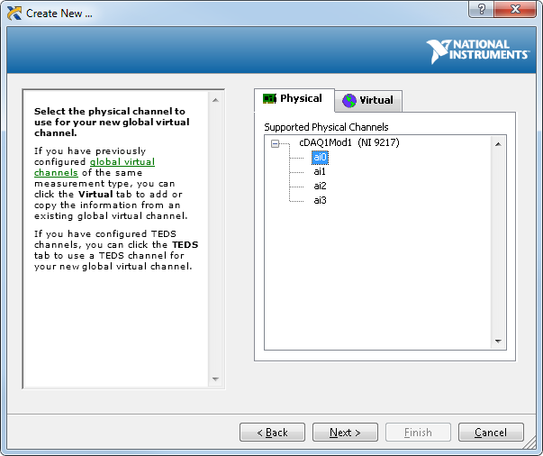 Figure 8
. Device Physical Channels
- Click Next and enter a name for the global virtual channel or leave the default.
- Click Finish and you should see the following screen in NI MAX:
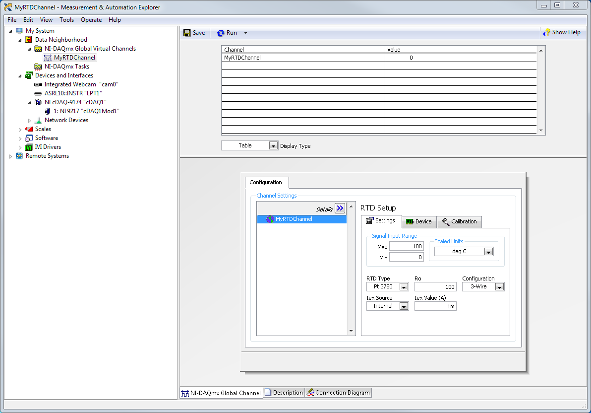 Figure 9
. Setting Up an RTD Channel in NI MAX
- On the settings tab, type in the minimum and maximum temperature values you expect to read from your RTD (0 to 100 °C by default).
- Select your RTD type, Nominal Resistance, Configuration, Iex Source, and Iex Value.
Testing the RTD Signal
With NI-DAQmx global virtual channels, you can preview your measurements.
- With NI MAX still open, click back on the NI-DAQmx Global Virtual Channel tab and click on the Run button. You see the temperature value of your RTD displayed at the top of the screen.
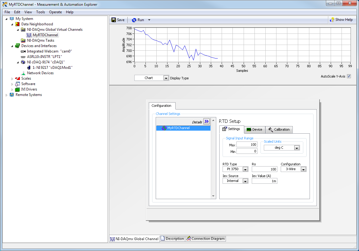 Figure 10
. Previewing an RTD Measurement in NI MAX
You can choose to view the signal in tabular form or as a graph by selecting Graph from the Display Type pull-down menu. You also have the option of saving your NI-DAQmx Global Virtual Channel should you wish to refer to this configuration screen again in the future.