Select the Appropriate Programming Model
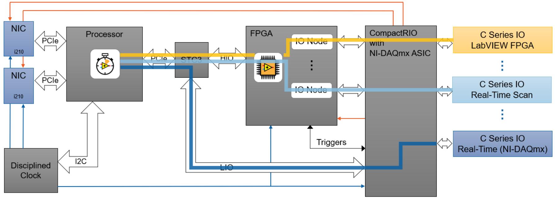
LabVIEW provides three programming models for CompactRIO systems. To select the appropriate programming model, it is important to understand how the data is transported from the physical input and output ports on the RIO target to the embedded system components. When using a CompactRIO, there are three ways to access I/O. In this tutorial, Real-Time (NI-DAQmx Mode) is used.
Real-Time (NI-DAQmx) Mode – This option brings two software experiences into one by combining the ease of use of NI-DAQmx and the low-level functionality of LabVIEW FPGA. It also simplifies system architectures by bringing the latest in synchronization and control technologies to the CompactRIO platform. To program a C Series module in this mode, place it under the Real-Time Resources folder in the LabVIEW project. This tutorial will cover how to set up a simple data acquisition using NI-DAQmx.
Real-Time Scan (I/O Variable) Mode – This option allows you to program the real-time processor of your CompactRIO system, but not the FPGA. In this mode, NI provides a predefined personality for the FPGA that periodically scans the I/O and places it in a memory map, making it available to the LabVIEW Real-Time Module. CompactRIO Real-Time Scan Mode is sufficient for applications that require single-point access to I/O at rates of a few hundred hertz. To program a C Series module in this mode, place it under the Real-Time Scan Resources folder in the LabVIEW project. Refer to
Take Your First Measurement in LabVIEW Real-Time for more information.
LabVIEW FPGA Interface Mode – This option allows you to unlock the real power of CompactRIO by customizing the FPGA personality in addition to programming the real-time processor, achieving performance that would typically require custom hardware. Using the LabVIEW FPGA Module, you can implement custom timing and triggering, offload signal processing and analysis, create custom protocols, and access I/O at its maximum rate. To program a C Series module in this mode, place it under the FPGA target in the LabVIEW project.
The following figure shows how each mode sends the I/O data through a unique path. For Real-Time (NI-DAQmx) mode, the data is read through the processor using NI-DAQmx VI’s. For Real-Time Scan (IO Variable) mode, the data is sent through the FPGA, but is ultimately accessed on the processor by dragging and dropping IO Nodes to the Real-Time VI. For LabVIEW FPGA mode, the I/O is read from directly from within the FPGA by dragging and dropping IO Nodes to the FPGA VI.
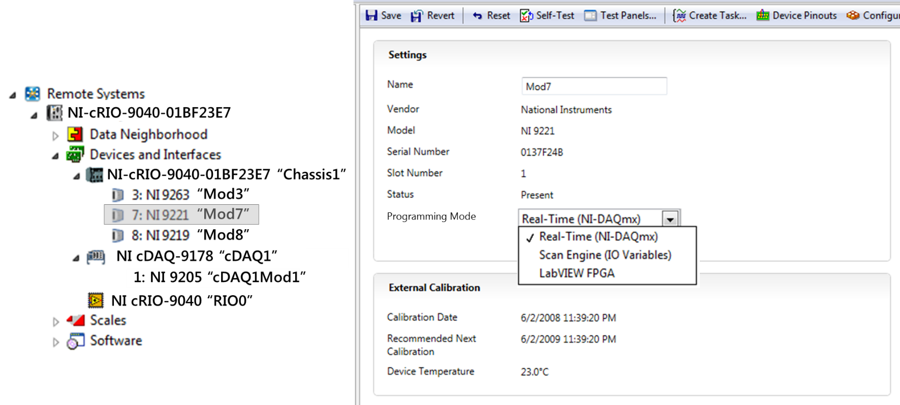
If you have the LabVIEW Real-Time Module, LabVIEW FPGA Module, and NI-DAQmx on your development computer, you can select which programming model to use on a per-module basis by placing the module under the appropriate heading in the project. The programming mode is indicated by the text next to the module in the LabVIEW project. You can also select which programming model to use by selecting from the drop-down menu in NI Measurement & Automation Explorer (MAX). For this tutorial, ensure that the programming mode on your CompactRIO hardware is set to Real-Time (NI-DAQmx).
Starting a New CompactRIO Project in LabVIEW
Begin by creating a new project in LabVIEW to manage your code and hardware resources.
- Create a new project in LabVIEW by selecting File»Create Project. Then select Blank Project. Save the project by selecting File»Save and entering a unique name, such as CompactRIO Using NI-DAQmx. Click OK.
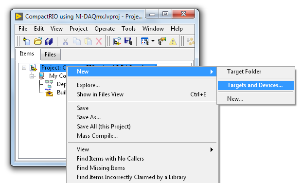
- The default project includes My Computer, which is where you can write code that runs on the Windows machine you’re currently developing on. Remember that a real-time target has a processor running a real-time OS, so it's effectively another computer. To write code that runs on that computer, you need to add another target to your project. Right-click on the Project item at the top of the tree and select New»Targets and Devices… to add a real-time system to the project.
- With this dialog, you can discover existing systems on your network or add a new system. If you have already configured your CompactRIO system in LabVIEW or in NI MAX, select Existing Target or Device, and Discover an existing target(s) or device(s). Expand the Real-Time CompactRIO folder and select your device, then press OK. If your device is connected to a remote subnet, you may need to connect via IP address. Select Specify a target or device by IP address and enter the IP address of your device. LabVIEW lists available hardware corresponding with the drivers you have installed. Since you installed the NI-RIO driver with your evaluation software, expand the Real-Time CompactRIO folder and then select cRIO-9045. Press OK.
- Confirm that your C-Series Modules appear under the Real-Time Resources section. In this tutorial, you are using an NI-9215 analog input module.
Acquire Data using the Real-Time NI-DAQmx API
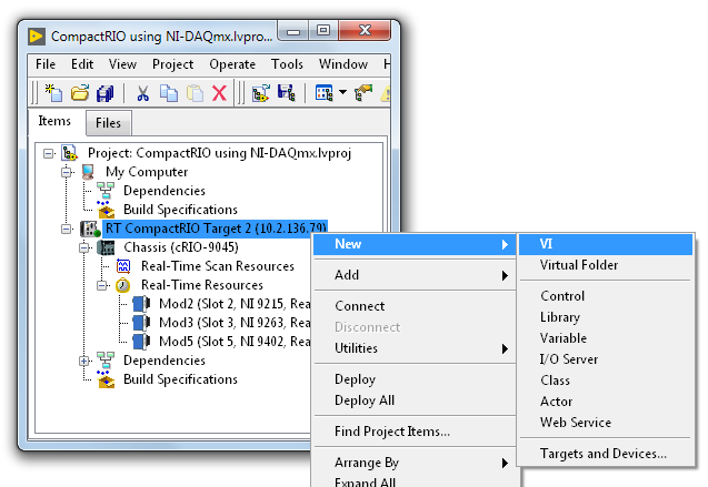
- You should now have a new LabVIEW project that contains your CompactRIO system, including the controller, chassis, and C Series I/O modules. In the LabVIEW project, right click on the CompactRIO real-time controller and select New»VI. Save the VI as DAQmx.vi. This VI is where you will perform your data acquisition and processing using NI-DAQmx.
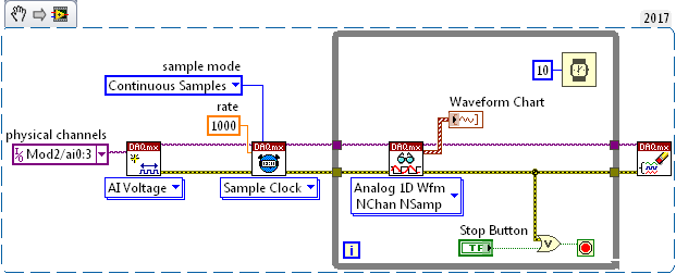
- Begin by creating a Virtual DAQmx Channel by right clicking on the Front Panel and navigating to Measurement I/O»DAQmx – Data Acquisition»DAQmx Create Virtual Channel. Drag this VI to the front panel.
- Right click on the Physical Channels input terminal of the DAQmx Create Virtual Channel VI and select Create » Constant. Click Browse and select all channels by holding down Shift and clicking through the items. This will allow us to read from all four analog input channels in one virtual channel. If you cannot see any channels, confirm that your device is connected, and that your individual modules are configured for Real-Time (NI-DAQmx) programming in NI MAX.
- Find the DAQmx Timing VI in the DAQmx – Data Acquisition palette and drop it on the front panel. Right click on the rate terminal and select Create»Constant. This is where you can set a custom sample rate for your acquisition. Ensure that this is set to 1000Hz. Repeat this process for the sample mode terminal, and choose Continuous Samples from the drop-down list. This will allow us to continuously take data.
- Create a While Loop. In the DAQmx – Data Acquisition palette, find the DAQmx Read VI, and place it inside the loop. Because you are reading multiple samples from four channels, click on the drop-down menu on the VI, and select Analog»Multiple Channels»Multiple Samples»1D Waveform (Samples).
- Open the Front Panel of your VI and create a Waveform Chart by right-clicking to open the palette, then selecting Silver»Graph»Waveform Chart (Silver). On the Block Diagram, connect the data terminal of the DAQmx Read to your waveform chart. This will display your waveform data. Add a Wait (ms) function and a stop button to your loop. Your final VI should look like the one below. Note: This screenshot is a VI Snippet that you can copy into LabVIEW by clicking and dragging to your block diagram.
- Run your VI. LabVIEW will connect to the CompactRIO, deploy the code, and then run the code on the real-time target. You can view the data on the waveform chart you have created.