Using the Dialog & User Interface VIs
LabVIEW includes the Dialog & User Interface VIs, which have limited options you can configure.
The One Button Dialog VI, Two Button Dialog VI, and Three Button Dialog VI display messages with buttons, as shown in the following illustration.
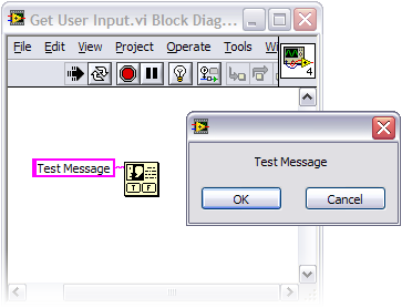
The Prompt User for Input Express VI provides more customization options, such as user input in the form of a string, number, or Boolean value. However, with this Express VI, the dialog box cannot display indicator values, and you cannot change the location of controls in the dialog box.
Creating Custom Dialog Boxes
The Dialog & User Interface VIs are useful when you need a dialog box for a simple application, but you should create a custom dialog box if an application requires a more complex dialog box.
To create a custom dialog box, arrange the front panel of a VI to make it look and behave like a dialog box. Then, you can call the dialog VI from the main application. Without any modification, these dialog boxes do not look like Windows dialog boxes, as shown in the following illustration.
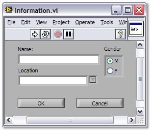
Open the attached Get User Input.vi to modify the appearance and behavior of a dialog box. Consider the following suggestions:
-
Use controls from the System palette.
-
Assign a custom name to the dialog box on the Window Appearance page of the VI Properties dialog box.
-
Configure each control on the dialog box with the Key Navigation tab of the Properties dialog box.
Refer to the LabVIEW Help for more information about how to modify the appearance and behavior of a dialog box.
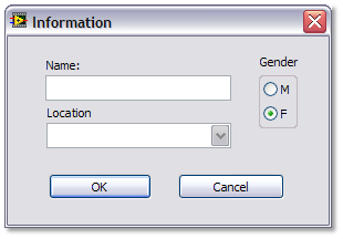
With these modifications, the dialog box looks more complete, as shows in the following image.
Programming the Custom Dialog Box
When you finish the front panel for the dialog box, you need to create the block diagram for the VI with an event based architecture. This architecture, as shown in the following image, allows for new additions to the code and keeps the code clean and manageable.
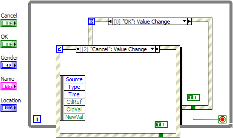
Complete the following steps to create an event case for any user interaction that causes an action with the Get User Input.vi.
-
On the block diagram, add a second event structure to the While Loop.
-
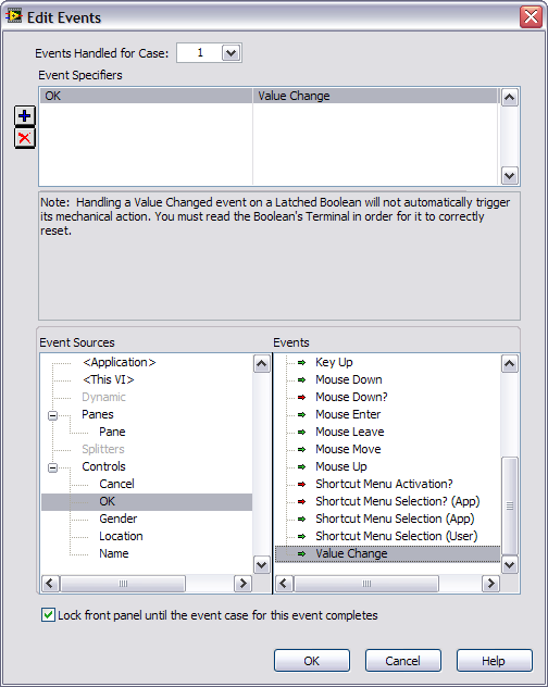
For the purposes of this tutorial, the event structure for the Cancel button is already programmed to close when a user clicks the Cancel button. For the dialog box to close when a user clicks the OK button, right-click the border of the event structure for the OK button and select Add Event Case from the pull-down menu to launch the Edit Events window, as shown in the following image.
-
Select OK in the Event Sources listbox and select Value Change in the Events listbox to program the dialog box to close when a user clicks the OK button.
-
Add a True Constant to the event structure for the OK button and wire the constant to the conditional terminal of the event structure, which causes the VI to close VI when a user clicks either button.
Note: The Timeout case for both event structures is present by default. You can ignore this case for the purpose of the tutorial.
-
When you configure these events, you need to specify the behavior for each event. To send the current control values to output indicators if the user clicks OK, add Gender, Name, and Location controls to the event structure for the OK button and wire them to the Gender, Name, and Location indicators. Do not wire the constants in the event structure for the Cancel button to send default null values if the user clicks Cancel.
The block diagram should be similar to the example in the following image.
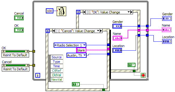
The three indicators on the right side pass data to a calling VI. Make sure that these indicators are not in the visible area of the front panel. The Wait Until Next ms Multiple Function inside the While Loop prevents the dialog box from consuming more resources than necessary. With this function, the code only executes 10 times per second. The Reinitialize to Default method ensures that each button using an invoke node is in the correct position when a user launches the dialog box.
Implementing the Custom Dialog Box
Once you program the dialog box, complete the following steps to configure it to work with the Main Application.vi.
-
To edit the connector pane of the Get User Input.vi, right-click the VI icon on the front panel and select Show Connector.
-
If you want to change the current terminals on the connector pane, right-click the VI icon again and select Disconnect All Terminals.
-
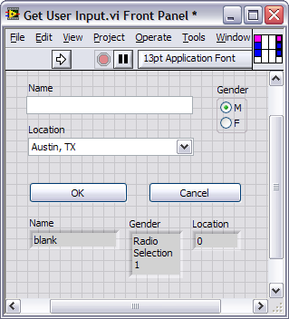
For the name, location, and gender indicators, click an indicator on the front panel and click an output on the connector pane. If you want to be able to set starting control values from the calling VI, click a control on the front panel and click an input on the connector pane. The terminal color changes to reflect the data type of the selected control or indicator. The complete connector pane should look similar to the connector pane in the following image.
-
Create a unique icon for the Get User Input.vi that makes it easy to identify. To modify the icon, right-click the connector pane from the front panel and select Edit Icon.
-
Create your own icon in the Icon Editor dialog box or use the Templates tab in the dialog box to find a template background for the icon.
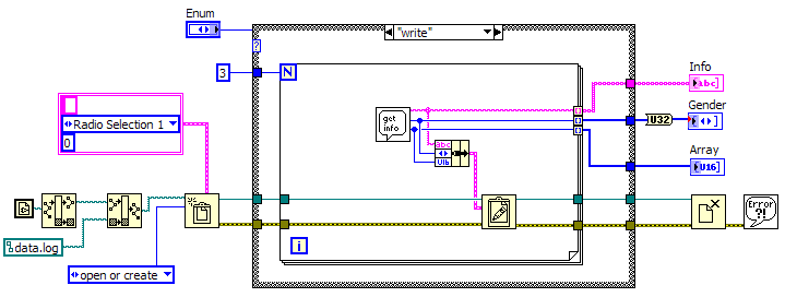
When you are ready to add a dialog VI to the main application VI, drag the dialog VI icon to the block diagram of the main VI or select Select a VI from the Functions palette to find the dialog VI. As shown in the attached Main Application.vi and the following block diagram image, you wire the outputs of the dialog VI to functions and indicators to use the information entered by the user.
When you create a dialog box, use the built in dialog VIs if you can, but for more complex applications, the custom dialog box gives you more options for configurable front panel design. The example VI attached to this tutorial is compatible with LabVIEW 8.0 or higher.