Carrier Recovery Fundamentals
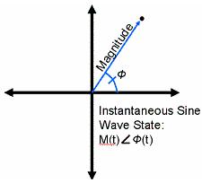
A QAM transmitter modulates a carrier signal with a specific phase and amplitude. A receiver, on the other hand, is only able to appropriately detect these transitions if is able to determine the phase and frequency of the originally transmitted signal. Thus, synchronization between the two is imperative. In an ideal world, both the transmitter and the receiver would operate perfectly synchronously. In other words, both would interpret the phase and frequency of the signal identically. However, real-world hardware is not ideal and a receiver cannot accurately lock onto precisely the same phase and frequency as a transmitter with some correction mechanism. To compensate for these non-deal characteristics, a phase-locked loop or PLL, is used to match the receiver and transmitter frequencies.
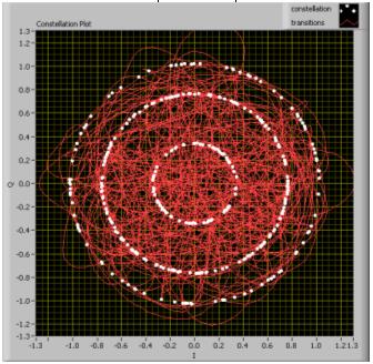
With a constellation plot, we are able to represent the amplitude and phase of each symbol. In addition, each symbol is overlaid on one another to illustrate the consistency with which we are able to recover the phase and amplitude of the carrier. Ideally, when the receiver’s PLL is able to perform carrier recovery, each symbol is shown distinctly in the constellation plot. However, when the carrier cannot be recovered due to channel noise or frequency error, this becomes evident in the constellation plot.
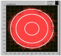
Below, we show a constellation plot where the symbols appear at the correct amplitude; however their phase is constantly changing. Since:
Frequency = dΘ / dt
Therefore, when the phase of the constellation plot is always changing, we are able to determine that the frequency estimation is incorrect.
In this specific instance, we have simulated this frequency error by introducing enough noise into the system to confuse the PLL. Even after the noise is removed, it is still possible to see how the PLL is not locking to the correct frequency.
Approaches to Carrier Recovery
There are two main parts to solving this issue of carrier recovery. These can be loosely broken into divisions: frequency recovery and symbol timing (phase) recovery. The first, frequency estimation is required in order for the receiver to lock onto the exact frequency of the transmitter. The second part, symbol timing recovery, requires the receiver to lock onto the exact phase of the transmitter. Symbol timing recovery enables the receiver to appropriately recover each symbol that has been generated by locking onto the exact phase of the transmitter. In addition, symbol timing recovery is perhaps more interesting because there are several approaches to its implementation.
Frequency Estimation
In an ideal communications system, both the transmitter and the receiver will operate at precisely the same frequency. However, in a real-world system, both the transmitter and receiver are susceptible to a variety of errors. As a result, the frequency of both must be synchronized. This occurs at the reliever end and starts with frequency estimation.
FFT Approach
The simplest approach to frequency estimation is simply to take an FFT of the incoming signal and identify the peak. This approach is simplistic and requires commonly used algorithms. However, the FFT approach suffers from one major drawback in that it requires significant processing time. As a result, it is seldom used in commercial applications.
Two Stage Algorithmic Approach
A second approach to frequency estimation is to use a two stage frequency estimation algorithm. This first stage roughly measures the frequency difference between the expected frequency and the observed frequency at the receiver. The second stage implements an additional algorithm to provide a even more precise estimation. This approached is utilized in LabVIEW’s modulation toolkit and is thus described in greater depth.
Course Frequency Offset Computation
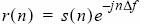
Course frequency compensation can be performed independent of the modulation scheme. The purpose of this stage in the frequency estimation process is to remove the frequency offset by operating directly on the complex-envelope input waveform. Mathematically, we can represent a complex-envelope modulated waveform with the following equation:
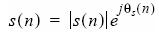
Moreover, when this is sampled at a specified sample rate Fs, we can further represent this as:
Since phase error results in a change in frequency, we can represent the frequency error as:

Again, F
s, represents the sample rate. Thus, to correct for this course frequency offset, we must apply ∆ƒ to our original complex-envelope waveform. In doing so, we can represent the complex waveform by the following equation:
Fine Frequency Offset Compensation
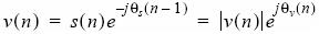
With fine frequency offset compensation, the mathematics are slightly more involved - although the approach is the same. Again, we represent the complex-envelope modulated waveform by the following equation:

In addition, this can be further expanded, when sampled at a symbol rate R, by the following equation:
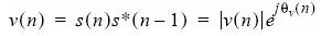
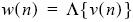
At this point, maximum likelihood detection is applied and represented by the equation:
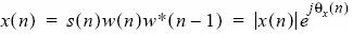
From here, we can represent the complex-envelope waveform by the following equation:
Again, with
Fs, representing the sample rate, we can represent the frequency offset by the following equation:

As a result, it is possible to represent the fine frequency offset with the equation:

Phase Estimation
Once the frequency error of the system has been accounted for, the carrier phase must be properly estimated to perform appropriate symbol recovery. In general, there are two approaches to phase estimation which can be broken into two categories: 1) non-decision directed approaches, and 2) decision directed approaches.
Non-Decision Directed Approaches
Two non decision approaches that we will discuss in this section are the phase-locked loop, and a related algorithm, the Costas loop.
A phase-locked loop (PLL) is a feedback algorithm designed to allow a receiver to synchronize with the specific phase of the received signal. To do this, it must first estimate the phase of this signal, and then adjust its own phase according. With each iteration, the phase error of the received signal is measured and used to proportionally control the offset of the next iteration. As a result, the receiver is able to precisely lock onto the phase of the transmitter over time.
The Costas loop is similar to the PLL, except that it uses two phase detectors to measure the phase of the received signal. The output of each of these detectors passes through a low-pass filter to another phase detector, which is used to control a voltage controlled oscillator. This is able to proportionally adjust the phase for the next iteration. The Costas loop is a recursive algorithm which is able to precisely lock the receiver to the transmitter over time.
Decision Directed Approaches
There are several decision directed approaches to phase recovery. These methods include a decision directed feedback loop, the minimum mean-square error method, and a maximum likelihood detection method. In this document, we will focus on the maximum likelihood detection mechanism implemented by the modulation toolkit in LabVIEW.
Maximum Likelihood Methods (MT Max Eye)
One approach to symbol timing in LabVIEW modulation toolkit is the Max Eye approach. Using this approach, the optimal sampling offset is calculated by choosing the offset which maximizes the opening in the eye diagram. However, this approach is susceptible to channel noise, which closes the eye diagram. Thus, in scenarios where this is significant channel noise, performing accurate carrier recovery is extremely difficult.
Frequency Error

As already mentioned carrier recovery Is essential to recover the frequency and phase information of the transmitted signal. To illustrate the importance of carrier recovery, we first show a constellation plot of a signal in which the frequency has not been properly been estimated. This can be done in LabVIEW by applying a significant frequency error. This can be done with the “Add Phase Noise” VI in LabVIEW (above). As a result of frequency error, we can see (below) from the circular rings indicate that the constellation plot is spinning. This behavior is indicative that the demodulator is unable to recover the appropriate frequency information for the transmitted signal.
Phase Error
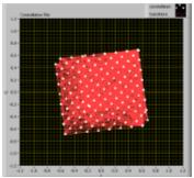
A second important characteristic of carrier recovery is correcting for phase error. In the image shown below, we can identify the problem of phase error specifically, because each of the symbols is repeatedly hitting the same location. This indicates that our frequency estimation is correct, otherwise, the constellation plot would be spinning. However, these locations are uniformly phase-shifted from an ideal symbol map. Thus, we can determine that the PLL still has a slight phase offset from the carrier signal.
Effect of Noise on Carrier Recovery
Channel Noise is fundamentally the greatest impairment to determining frequency phase information of a transmitted signal. Because noise skews phase and amplitude information, you will often see the constellation plot begin to spin as the noise level increases. Under normal circumstances, the carrier recovery mechanism is robust enough to account for moderate phase and frequency error. However, under extreme circumstances, even the best algorithmic approaches cannot accurately decipher this information.
Conclusion
As this document illustrates, carrier recovery is a significant aspect of digital communications systems. Moreover, the phase-lock loop performs a significant role in allowing the receiver to accurately determine both the phase and frequency of the carrier signal. Finally, we have observed that channel noise is one of the largest impairments to carrier recovery and that significant noise can prevent carrier locking from occurring successfully.