Example Summary
The attached examples of LabVIEW 2018 show how to:
- Programmatically get the DAQ module names using DAQmx System and Device property nodes.
- Create the check boxes, with either all the channels or with one channel deleted, using clusters.
- Get the index position of the check box channels you selected.
- Use the index position to programmatically select the correct channel from the DAQmx System and Device property nodes
- Combine these selected channels together and pass into the DAQmx Create Channel.vi.
A) Programmatically get DAQ Channel Names
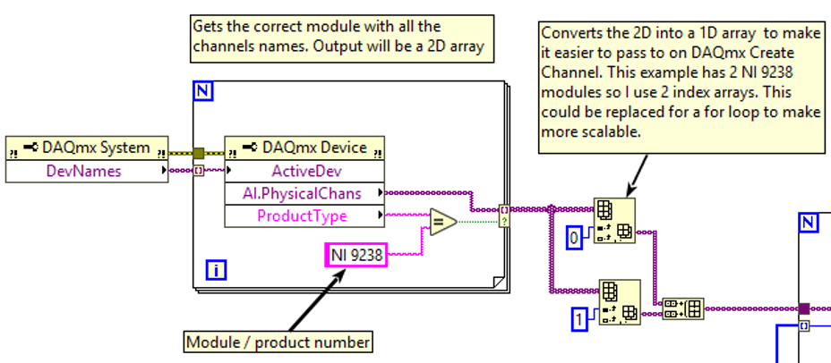
- Place the DAQmx System and DAQmx Device property nodes on the Block Diagram. Put a For Loop around the DAQmx Device property node and wire the DevNames output from the DAQmx System property node to the ActiveDev input of the DAQmx Device property node. Keep the auto indexed tunnel (Enable Indexing).
-
Resize the DAQmx Device property node to select the required DAQ I/O Type, i.e. AI.PhysicalChans or DO.Lines, and wire to the output of the For Loop. Right click on the tunnel and change the Tunnel Mode to Conditional.
-
Resize the DAQmx Device property node and add a ProductType output. Create a condition using the product name and wire to the boolean input on the conditional terminal. i.e. If the product type equals the NI-9238, then output the AI.PhysicalChans.
-
The output of the For Loop with the conditional terminal will be an array, either a 1D or 2D depending on the number of DAQ hardware product types you configured. If its a 2D array, you need to manipulate the array into a 1D array.
-
In the examples, there are 2 NI-9238 so a 2D has been created, with one module per row. Use the Index Array functions to extract each row from the 2D array, and the Build Array set to Concatenate Inputs to build into a 1D array.
-
Wire to the input of a For Loop and Disable Indexing tunnels.
B) Create Check Boxes
In parallel to Section A, we need to create the check boxes.
-
Create a cluster which contains boolean buttons or check boxes. This can either be on the Front Panel or Block Diagram. It should have the same number of channels or less than the module you are configuring it for.
-
Wire the cluster to a Cluster to Array on the Block Diagram.
-
If you are keeping all the channels, more to step 4. Otherwise, go to step 3.1.
-
If you want to remove (or hide) a channel from the user, delete the channel from the cluster. For example, a NI-9238 has 4 channels and if I don't want my user to select ai1, delete this from the cluster.
-
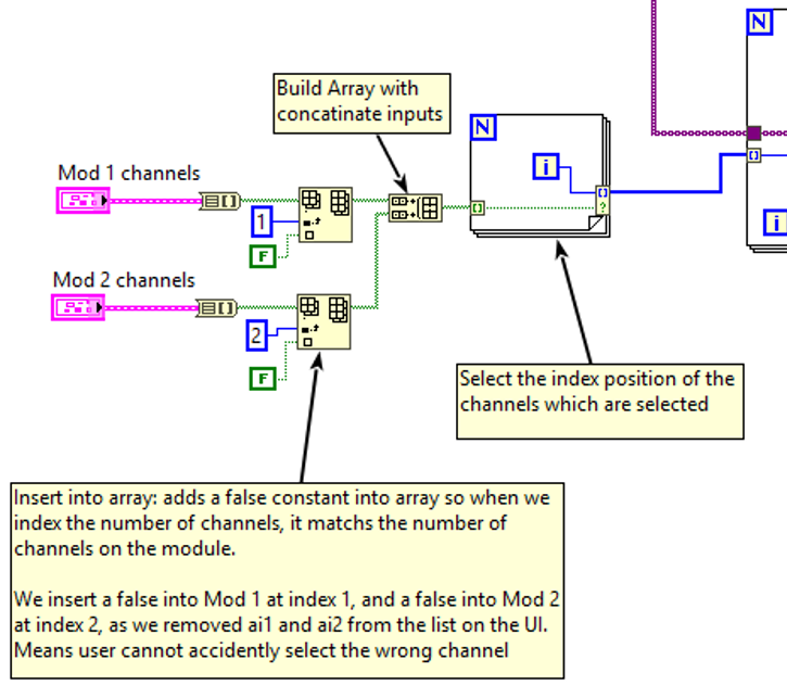
Wire the output of the Cluster to Array to a Insert into Array.
-
Wire a numeric constant to the index of the Insert into Array and write the value of the index of the channel you want to hide. For example, if you removed ai1, use a value of 1 in the constant. Wire a False constant to new element input.
-
We do this because we want to ensure the array has the same number of elements as the channels for the module.
-
Wire the output of the Insert into Array into a Build Array set to Concatenate Inputs
-
Repeat these steps for all the modules you need.
-
Create a For Loop. Pass the output of the Build Array into the For Loop, and Enable Indexing.
-
In the For Loop, wire the index counter to the output. Right click on the tunnel and change the Tunnel Mode to Conditional.
-
Wire the input (the output from the build array) to the condition on the Conditional Tunnel.
-
This will create a 1D array of the index positions check boxes (DAQ channels) you selected so that you can extract the same index position from the 1D array outputted from Section A.
-
Wire the output of the For Loop in step 4 to the input of the For Loop created at the end of Section A. Enable Indexing on the input.
C) Combine A) and B) to Create the Input to the DAQmx Create Virtual Channel
This section combines the channels together to wire into one DAQmx Create Virtual Channel. Further manipulation will be needed to separate for multiple DAQmx Create Virtual Channels.
-
There should be a For Loop with the inputs to the loop being the 1D physical channel array from Section A (with the auto index disabled) and index position from Section B (auto indexing enabled).
-
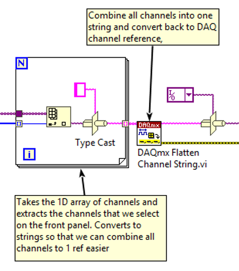
In the For Loop, create a Index Array function, with the input to the Index Array being the 1D array of DAQ physical channels and the index input being from the index position input.
-
Wire the output of the Index Array to a Type Cast function, which has a string constant connected to the Type input.
-
Wire the output of the Type Cast to the output of the For Loop and change the Tunnel Mode to Indexing. The output should be a 1D array.
-
This will allow us to extract the DAQ channels based on the index position, which in turn is based on the user selection.
-
Create a DAQmx Flatten Channel String.vi and wire the output of the For Loop to the input. This will combine the elements in the 1D array into the correct format for a DAQmx Physical Channel.
-
Create a Type Cast with a Physical Channel constant wired to the Type input.
-
Wire the output of the DAQmx Flatten Channel String.vi to the input of the Type Cast.
-
The output of the Type Cast can be wired to the DAQmx Create Virtual Channel.vi and you can continue with you DAQ application.