Low-Level Measurement Setup
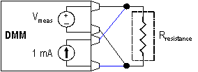
The best setup for low resistance measurements is the 4-wire setup. A 4-wire setup uses four leads: two leads to drive current through a resistance and two leads to measure the voltage drop across that resistance. Traditional 4-wire measurements require that the power is off in the circuit so that the measured voltage drop is only due to the supplied current. Thus, traditionally, the power to a circuit must be turned off before any measurements are taken. Figure 1 illustrates a 4-wire setup. The black-colored leads measure the voltage drop. The blue-colored leads connect the test current, which is 1 mA in the 100 Ω range.

Figure 1. Digital Multimeter Setup
In every resistance measurement, the digital multimeter must supply a test current (1 mA in this setup) and then measure the voltage drop across the unit under test. The measured voltage drop is then used in the calculation for resistance; thus, its accuracy is very important. This accuracy can be negatively affected in passive, power-on, in-circuit resistance measurements, such as power line resistance. This tutorial discusses possible sources of error in four measurement methods.
The four comparison measurement methods are:
- No Compensation
- Approximated Offset
- Measured Offset
- Offset Compensated Ohms (OCO)
Power Line In-Circuit Resistance
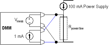
In-circuit measurements can have offset voltages because they often involve measuring resistance in the presence of a large voltage, for example, power supply bus resistance with the power on, as shown in Figure 2. With a traditional digital multimeter, you must make these types of measurements with the power off or you introduce very large errors into the system. For this example, the power line resistance (Rpower line) is assumed to be 10 mΩ.

Figure 2. Power Line In-Circuit Resistance Measurement
Case 1: No Compensation
The measured voltage is equal to the line current times the power line resistance plus the test current times the power line resistance. If there is 100 mA of current in the supply bus, the measured voltage is 100 mA times the power line resistance plus 1 mA test current times the power line resistance. With a power line resistance of 10 mΩ, the measured voltage is 1.01 mV.
V
meas = Line Current x R
power line + Test Current x R
power lineV
meas = 100 mA x R
power line + 1 mA x R
power lineV
meas = 1.01 mV
The calculated or measured resistance is equal to the measured voltage divided by the test current. This measured resistance is 100 times greater than the actual value of 10 mΩ.
Figure 3. Measured Power Line Resistance with No Compensation
Rmeas = Vmeas/Test Current
Rmeas = 1.01 mV/1 mA
Rmeas = 1.01 Ω
This is a measurement that cannot be done without some kind of offset compensation.
Case 2: Approximated Offset
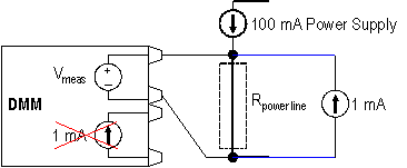
To get an accurate resistance measurement, you must remove the effect of the 100 mA power supply from the measurement. One way to do this is to approximate the error by estimating the current. There are two drawbacks to this type of adjustment. First, you must use an external current excitation source because voltage, not resistance, must be measured. The digital multimeter setup is shown in Figure 4.

Figure 4. Digital Multimeter Setup for Voltage Measurement with External Current Supply
Second, you must make additional calculations by hand to obtain resistance. The measured voltage still includes the error due to the power supply, but when calculating the resistance, you can remove an estimated voltage. The major disadvantage to this method is that the actual error is not known.
V
meas = Line Current x R
power line + Test Current x R
power lineR
calc = (V
meas - Estimated Power Line Error)/Test Current
Case 3: Measured Offset
You can use another method to overcome this disadvantage - measure the actual power line error voltage and then take it out of the resistance calculation. With a traditional digital multimeter, the drawbacks include:
- Multiple voltage measurements
- An external current excitation source
- Additional calculations that must be done by hand
The same in-circuit power line resistance application using the measured offset technique requires the following steps:
- Take a voltage measurement with an external current supply (as shown in Figure 4).
- Take a second voltage measurement with no current excitation as shown in Figure 5. This measurement effectively measures the power line error in the system.
- Use the difference of the voltages to calculate resistance.
Figure 5. Digital Multimeter Setup for Voltage Measurement with No Current Excitation
The calculations for this method are as follows. The voltage drop across the power line is again 100 mA times the power line resistance plus 1 mA test current times the power line resistance. The measured voltage of 1.01 mV is the same as in the previous traditional non-compensated measurement.
V
meas #1 = Line Current x R
power line + Test Current x R
power lineV
meas #1 = 100 mA x R
power line + 1 mA x R
power lineV
meas #1 = 1.01 mV
With the second measurement using the measured offset technique, the 1 mA test current is not used, and so the measured voltage changes. The voltage drop across the power line is only due to the 100 mA power supply and so only that value is measured.
V
meas #2 = Line Current x R
power lineV
meas #2 = 100 mA x R
power lineV
meas #2 = 1.00 mV
The difference in the two measured voltages represents the voltage drop across the power line due to the test current. This voltage is divided by the test current to calculate an accurate resistance for the power line. Thus any error due to the power supply current is removed.
V
calc = V
meas #1 - V
meas #2V
calc = 1.01 mV - 1.00 mV
V
calc = 0.01 mV
R
meas = V
calc /Test Current
R
meas = 0.01 mV/1 mA
R
meas = 0.01 Ω
Case 4: Offset Compensated Ohms (OCO)
A final method incorporates the accuracy of the measured offset method but maintains the simplicity of the no compensation technique. This method, called offset compensated ohms (OCO), is available on the NI 4070 FlexDMM devices. It overcomes the requirements of multiple voltage measurements, external current excitation sources, and additional calculations, yet you can still use it to measure the actual error and take it out of the resistance measurement.
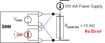
Once enabled and without any additional user interaction, OCO invokes an NI 4070 FlexDMM to take two resistance measurements but with the test current source off during the second measurement. The first measurement features the voltage drop across the power line including that from the supply current. During the second measurement, the current source is turned off so the voltage drop across the power line is only due to the power supply, as shown in Figure 6. The NI FlexDMM then subtracts the second measurement from the first to determine the OCO voltage (VOCO). You then use this voltage to determine the correct resistance value.

Figure 6. NI 4070 FlexDMM - Second OCO Measurement with Internal Excitation OFF
V
OCO = V
meas #1- V
meas #2V
OCO = 1.01 mV - 1.00 mV
V
OCO = 0.01 mV
R
meas = V
OCO/Test Current
R
meas = 0.01 mV/1 mA
R
meas = 0.01 Ω
Summary
Table 1 is a comparison of the methods to improve the accuracy of low-level, in-circuit resistance measurements, including the OCO technique on an NI 4070 FlexDMM.
Table 1. Comparison of the Methods to Improve the Accuracy of Low-Level, In-Circuit Resistance Measurements
| | Case 1: No Compensation | Case 2: Approximated Offset | Case 3: Measured Offset | Case 4: Offset Compensated Ohms (OCO) |
| Number of Measurements | 1 | 1 | 2 | 1 |
| External Current Supply | No | Yes | Yes | No |
| Accuracy | OK | Better | Best | Best |
| Possible Error | 100X | Less than 100X | Negligible | Negligible |
| Sources of Error | No compensation | Bad estimate | No procedural error | No procedural error |
| Complexity | Easy | Moderate | Difficult | Easy (no setup changes) |