Online and Offline Vibration Analysis
LabVIEW has an extensive library of order analysis functions available in the Sound and Vibration Measurement Suite. These tools are very useful for performing online analyses of vibration data. The term online essentially means that the vibration analysis is done at the time of acquisition. DIAdem's order analysis capabilities are a great solution for offline, interactive vibration data management. Offline analysis is done after the acquisition takes place, and the raw vibration data has been stored in a file or a database. DIAdem is a great solution for accessing test data saved in files and databases while also providing an excellent environment for creating sophisticated waterfall plots and 3D surface graphs that are required to interpret noise or vibration data. DIAdem, along with the Joint Time Frequency and Order Analysis tool, delivers an easy to use, non-programming approach to manage, inspect, analyze, and report your vibration data.
Overview of Analysis Types
There are three primary types of noise or vibration spectra that are examined when doing analysis on rotating machinery: Joint Time Frequency Spectrum, Order Analysis Frequency Spectrum, and Order Analysis Order Spectrum.
Joint Time Frequency Spectrum
Joint-Time Frequency analysis divides a data set into time intervals and performs a Fast-Fourier Transform (FFT) on the data in each time interval separately. This enables you to inspect how the frequency content of a signal develops over time. In the below figure Frequency is displayed on the 'X' axis, Time on the 'Y' axis, and the frequency magnitudes on the 'Z,' or intensity, axis. You can easily identify that the frequency of this signal peaked at about the 1.5 second mark.
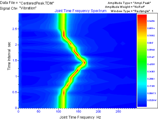
Figure 1. Joint Time Frequency Spectrum Graph
Order Analysis Frequency Spectrum
For the Order Analysis Frequency Spectrum case, the magnitude of the frequency content is examined slightly differently. In the figure below, Frequency is displayed on the 'X' axis, Rotational Speed (RPM) on the 'Y' axis, and frequency magnitudes on the 'Z,' or intensity, axis. This enables you to inspect how the vibration magnitudes track with Rotational Speed. For example, as an engine is run from startup (0 RPM) to idle speed (1000 RPM), the vibration the engine experiences changes at different RPM levels. Order analysis enables you to identify the critical rotational speeds that drive the noise or vibration of the UUT, perhaps to examine natural frequencies or other design problems.
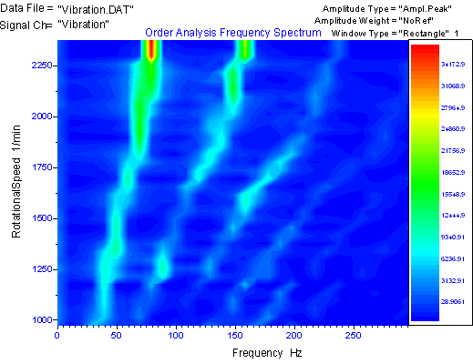
Figure 2. Order Analysis Frequency Spectrum Graph
Order Analysis Order Spectrum
The Order Analysis Order Spectrum case is very similar to the Order Analysis Frequency Spectrum case. Its only fundamental difference is that instead of having frequency on the 'X' axis, a quantity called order is placed there. Order simply represents the frequency of the vibration divided by the instantaneous rotational frequency of the UUT. This enables you to easily identify relative overtone amplitudes of the rotational speed as the rotation speed develops.
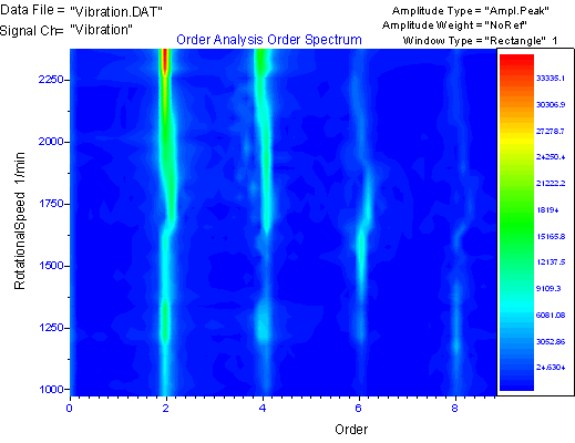
Figure 3. Order Analysis Order Spectrum Graph
Introduction to the Tool
All of these graphs were generated by the Joint Time Frequency and Order Analysis tool in DIAdem. The tool is essentially a collection of DIAdem resource files (VBScript files, VAS files, and SUDialog source files), which combine to form a simple, interactive user interface that resides in the DIAdem environment. The tool enables you to change graph axis limits, analysis types, report templates, and other analysis parameters very quickly and easily.
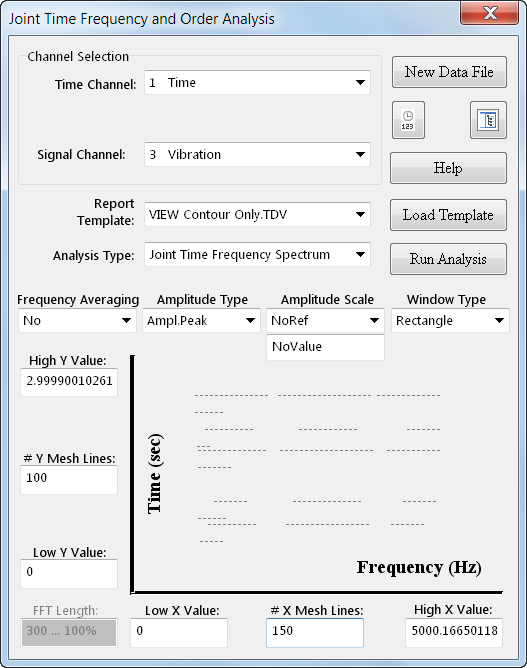
Figure 4. The Joint Time Frequency and Order Analysis Tool User Interface
The Joint Time Frequency and Order Analysis tool consists of three main components: Joint-Time Frequency Spectrum, Order Analysis Frequency Spectrum, and Order Analysis Order Spectrum. One way to visualize the difference in these analyses is to look at what data is generated and displayed.
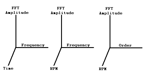
Figure 5. Main Analyses Provided by the Tool: Joint-Time Frequency Spectrum (Left), Order Analysis Frequency Spectrum (Center), and Order Analysis Order Spectrum (Right)
To switch between these components, simply select the type of analysis in the Analysis Type pull-down box. Switching between these components will, as appropriate, make certain components visible/invisible on the dialog. There is one additional function that is provided by the tool: the RPMs Channel from Tach. Channel selection. This function converts a tachometer pulse or rotary encoder channel into an RPM channel. For more information, see the Additional Tool Functions section of this document.
There are many Automatic Axis Value Checking routines that are built into the tool. Due to the nature of the analysis algorithms, there are many limitations on what values can be put into the axis high, low, and mesh line input boxes. There are several routines built into the tool that will automatically check and prevent illegal values from being placed into the axis value boxes.
Installing and Using the Tool
As previously mentioned, the Joint Time Frequency and Order Analysis tool is essentially a collection of DIAdem resource files (VBScript files, VAS files, and SU Dialog source files). There is no actual 'installation' for the tool, all that is necessary is to have the DIAdem software. If you do not have DIAdem currently, the tool is fully functional with the Evaluation Version. All that is necessary is to download the example program to your computer and extract the files to any directory. The tool will then be ready to use.
To open and run the tool:
- Open up DIAdem and select 'SCRIPT,' the automation panel of DIAdem. A blank VBScript file will be present on the screen.
- Select File»Open. . . or click the Open button on the toolbar. A dialog box should appear.
- Make sure that VBScript (*.VBS) is selected in the Files of Type box. Navigate to the directory where you downloaded and extracted the files. Select the script named Time Frequency Order Analysis.VBS and select Open.
- To run the tool, now click the 'Run Script' icon on the toolbar, or push Ctrl-F5.
The tool will now be running on your screen. If there was not any data loaded into DIAdem when the tool was launched, it will automatically prompt you to load a data set. To load a new data set at any time, simply click the New Data File button. You can now perform the three vibration analyses on your data. Any registered DIAdem file type, whether it’s a built in format (*.DAT, *.TDM, *.LVM) or a custom format, will be able to be loaded and used.
To follow along with this tutorial, load the Vibration.DAT data set, located in the Sample Data sub-directory of the tool.
Joint Time Frequency Analysis
A screen shot of the dialog when Joint Time Frequency Spectrum is selected is shown below:
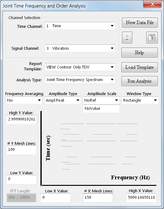
Figure 6. Joint-Time Frequency Spectrum Dialog
To perform this analysis, set the Time Channel and Signal Channel boxes to the Time and Vibration channels. When you select these channels, the frequency and time scale boxes should be automatically populated with suggested values.
- Select the View Contour Only.TDV layout under the Report Template input. Any selection, however, is appropriate for this analysis.
- Leave the Frequency Averaging, Amplitude Type, Amplitude Scale, and Window Type boxes as their defaults. For more information about these inputs, click the Help button and select 'Joint Time Frequency Analysis.'
- The values for the data ranges (High Y Value, # Y Mesh Lines, etc) should be automatically populated, but they could be changed if desired. If an invalid value is placed in one of the boxes, it will be coerced into a valid value.
- Click the Run Analysis button. This will generate all of the data and automatically display the analysis results using the template selected in Report Template.
- To show and hide the data portal, click on the Portal button, located on the right hand side below the New Data File button.
- To change the layout displayed, simply change the selection in the Report Template box and click Load Template.
Order Analysis Frequency Spectrum
A screen shot of the dialog when Order Analysis Frequency Spectrum is selected is shown below:
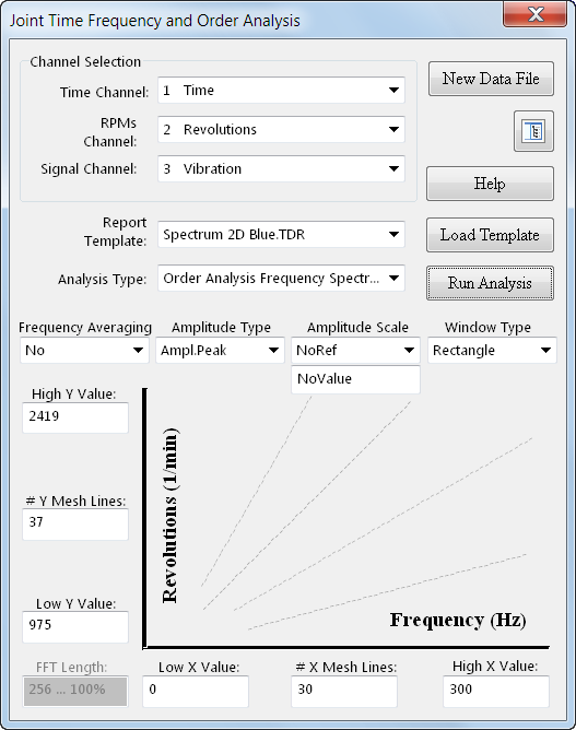
Figure 7. Order Analysis Frequency Spectrum Dialog
To perform this analysis, set the Time Channel, RPMs Channel, and Signal Channel boxes to the Time, Revolutions, and Vibration channels respectively. If you do not have an RPM channel in your data set, but rather have a tachometer pulse or rotary encoder channel, you can convert that channel into an RPM channel. See the Additional Tool Functions section for how to use this routine. When you select these channels, the Frequency and Revolutions scale boxes will automatically populate with suggested values.
- Select the Spectrum 2D Blue.TDR report under the Report Template input. Any selection, however, is appropriate for this analysis.
- Leave the Frequency Averaging, Amplitude Type, Amplitude Scale, and Window Type boxes as their defaults. For more information about these inputs, click the Help button and select 'Order Analysis Frequency Spectrum.'
- The values for the data ranges (High Y Value, # Y Mesh Lines, etc) should be automatically populated, but they could be changed if desired. If an invalid value is placed in one of the boxes, it will be coerced into a valid value.
- Click the Run Analysis button. This will generate all of the data and automatically draw the data on the report template selected in Report Template.
- To show and hide the data portal, click on the Portal button, located on the right hand side below the New Data File button.
- To change the layout displayed, simply change the selection in the Report Template box and click Load Template.
Order Analysis Order Spectrum
A screen shot of the dialog when Order Analysis Order Spectrum is selected is shown below:
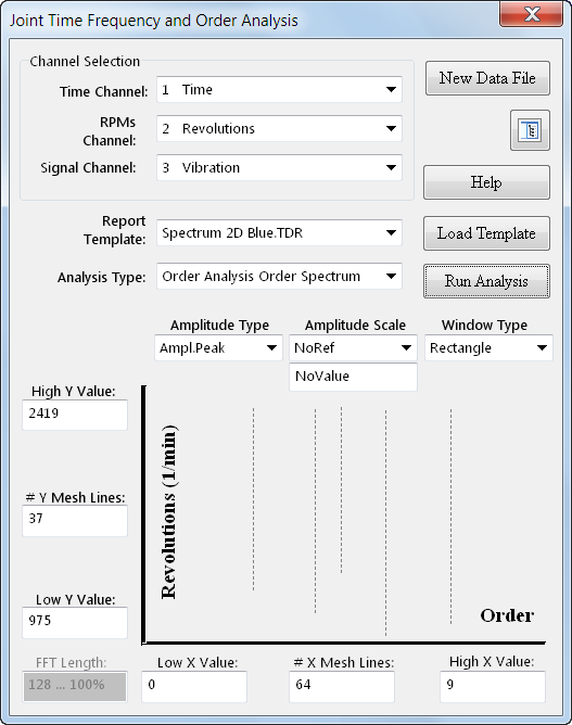
Figure 8. Order Analysis Order Spectrum Dialog
To perform the analysis, set the Time Channel, RPMs Channel, and Signal Channel boxes to the Time, Revolutions, and Vibration channels respectively. If you do not have an RPM channel in your data set, but rather have a tachometer pulse or rotary encoder channel, you will can convert that channel into an RPM channel. See the Additional Tool Functions section for how to use this routine. When you select these channels, the Order and Revolutions scale boxes will automatically populate with suggested values.
- Select the Spectrum 2D Blue.TDR report under the Report Template input. Any selection, however, is appropriate for this analysis.
- Leave the Amplitude Type, Amplitude Scale, and Window Type boxes as their defaults. For more information about these inputs, click the Help button and select 'Order Analysis Frequency Spectrum.'
- The values for the data ranges (High Y Value, # Y Mesh Lines, etc) should be automatically populated, but they could be changed if desired. If an invalid value is placed in one of the boxes, it will be coerced into a valid value.
- Click the Run Analysis button. This will generate all of the data and automatically draw the data on the report template selected in Report Template.
- To show and hide the data portal, click on the Portal button, located on the right hand side below the New Data File button.
- To change the layout displayed, simply change the selection in the Report Template box and click Load Template.
- Now let's zoom in on the dominant order feature of the order spectrum graph. Input 0 and 3 into the Low X Value: and High X Value: boxes respectively, and then click the Run Analysis button. This will re-generate the graph zoomed in on the specified X and Y ranges. Zooming in using the Axis Value Range boxes (Low X Value, High X Value, etc) will yield improved resolution and detail for the region of interest. Interactively change the Axis Value Range boxes to examine other features of the graph.
Additional Information
- As previously mentioned, there are several routines built into the tool that will automatically check and prevent illegal values from being placed into the axis value boxes. These routines are executed in one of two ways:
- Place the values that you would like in the boxes and select Run Analysis. Before the analysis is run, the values for the axis ranges and mesh densities are checked (and coerced if necessary) against valid values. When the analysis is done and the report is shown, the actual values used during the analysis will be populated in the axis value boxes.
- Place a desired value into one of the boxes and click on an ‘open area’ (not on another control) of the tool. When the tool receives the Dialog.Click event, the values inside of the boxes are run through the axis value checking routines. If any of the values are out of range or not allowed, the corrected value will be placed in the appropriate box.
- As a general rule, the greater number of mesh lines will give you finer resolution, but will also make the analysis take longer.
- Changing the scale values (High Y Val, # Y Mesh Lines, etc) and clicking on Load Template will have no effect. You must re-calculate the data sets by clicking Run Analysis for those changes to show up on the report.
- To load a new data set at any time, simply click the New Data File button.
Additional Tool Functions
Along with the three main functions of the Joint Time Frequency and Order Analysis tool, there are two additional features added for ease of use and visualization. the RPMs Channel from Tach. Channel function, and the Toggle Time Channel DateTime function.
RPMs Channel from Tach. Channel
When doing order analysis, it is necessary to have an RPM channel that corresponds with your time data. There must be a one-to-one correlation between each point in time and an RPM value at that time in order for the order analysis functions to work. Frequently, when doing vibrational data acquisition with a Dynamic Signal Acquisition device, an RPM channel is not available. Instead, an analog waveform of a tachometer pulse signal or a rotary encoder signal is acquired, which can then later be converted to an RPM channel. The Joint Time Frequency and Order Analysis tool provides this functionality in an easy to use, interactive interface.
A screen shot of the dialog when RPMs Channel from Tach. Channel is selected is shown below:
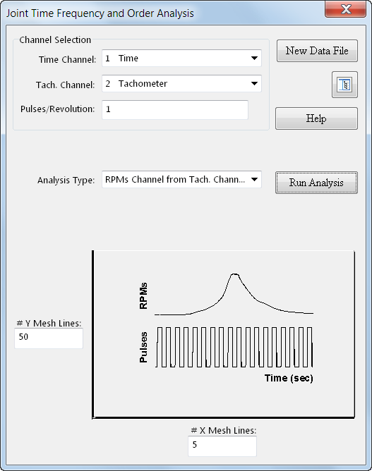
Figure 9. RPMs Channel from Tach. Channel Dialog
To use this function:
- Click the New Data File button and load the CenteredPeak.TDM, located in the Sample Data sub-directory.
- Select the Time Channel and the Tach. Channel as Time and Tachometer in the pull down boxes.
- Input 1 into the Pulses/Revolution box. This is the number of pulses per revolution that your tachometer pulse provides.
- Input the values for the #Y Mesh Lines and # X Mesh Lines. For this function, these values represent the frequency of a low-pass filter that is applied to the data. In most cases, the default values are acceptable. For more information about these parameters, see the section for RPMs Channel from Tach. Channel in the help file for the tool.
- Click on Run Analysis. The RPM channel will be created with the name R.P.M.s. Also, a preview of the created RPMs channel will appear inside DIAdem.
This channel can now be used in the RPMs Channel pull down box when performing the order analysis functions.
Toggle Time Channel DateTime
For visualization, sometimes it might be necessary to convert your time channel into a DIAdem Date/Time channel. The Joint Time Frequency and Order Analysis tool provides a quick method for converting your time channel.
To use this function, simply click the  button to convert in the Time Channel to and from a DIAdem Date/Time channel. Click the button again to switch back to relative seconds display.
Conclusion
This tool takes advantage of DIAdem's technology: the ability to interactively manage, inspect, analyze, and report data. By using DIAdem VBScripts, we can perform complicated frequency analyses on very large data sets, and in seconds view and inspect our results. The tool provides an easy to use, non-programming interface to performing three common types of frequency analysis: joint time frequency analysis, order analysis frequency spectrum, and order analysis order spectrum. The tool also provides additional functionality to convert tachometer data into RPM data and to convert back and forth between time channels and DIAdem Date/Time channels.