Launch Vivado
Note: Vivado 2013.4 support is for Windows 7 only.
Open the Xilinx Vivado Tool directory by navigating to C:\NIFPGA\programs\VivadoXXXX_Y\bin\vivado.bat, where XXXX_Y is the version of Vivado to be opened.
Create a Managed IP Project
You'll be asked to create a new project and follow the wizard to complete this process. The Xilinx FPGA used on the 6591R is the xc7k410tffg900-3, and the 6592R uses the xc7k410tffg900-2. Select one of the two to complete the new project creation.
Once the new project is created, follow the process of adding IP to your project through the IP Catalog inside of Vivado.
Choose Aurora IP from the IP Catalog
At this point, choose the encoding scheme you desire. We will work with the 64b/66b IP. Double click the IP to open up the customization window for the IP core. You may be asked to Generate Output Products at this time. If so, select Generate.
Modify Core Properties
From the User Manual, NI recommends not using AXI4-Lite for DRP, so we select Native for this step. For this particular example, all other core options will be left default.
On the GT Selections tab, implement one port on Quad 3. Per the location information for the ports on the 6591R/92R, select the following:
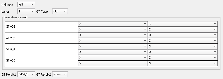
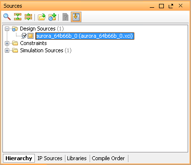
When you are finished, select OK and Generate the output products. You are left with a synthesized IP core (.xci file) shown below.
Note: Our sample projects come with a .xci file that contains all the core settings used for the sample project CLIP.
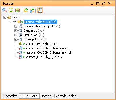
This is how it looks in the IP Sources tab:
Create .edf Netlist Files
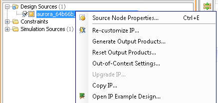
If the IP core you are using is written in Verilog, a netlist must be created to successfully compile the design. Right click the .xci file in your Sources window and select Open IP Example Design.
In the new Vivado window that pops up, select the top level VI for which you would like to generate a netlist, and then click Run Synthesis on the left hand side.
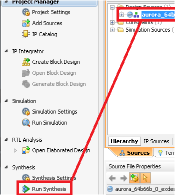
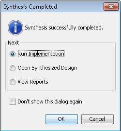
Once the synthesis completes, select Open Synthesized Design in one of the following ways:
- In the pop-up window
- Select Open Synthesized Design on the left hand pane under Synthesis
- Open the Design Runs tab and right-click, then select Open Synthesized Design
Example of the window pop up where Open Synthesized Design may be selected:
To write the .edf file, use this Tcl command in the project:
write_edif <name of entity>.edf
This creates the netlist that you will need to use when you import the IP core into your LabVIEW project. You can find it at the location indicated by the Tcl Console window output.
For the Aurora sample project, several .edf files were created with this method, including the following files:

To build .edf files for those specific blocks, you will need to stay in the Synthesized Design window in Vivado, where you can view several cells associated with the design in the Netlist window:
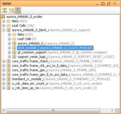
To create an .edf for an associated cell, enter the following command:
write_edif -cell <name of cell> <file name>.edf
For example, to create the clock_module.edf, the command would be:
write_edif -cell clock_module_i aurora_64b66b_clock_module.edf
Note: You may have to specify a longer path name depending on where the cell is located in your project. For example, clock_module_i may be under aurora_64b66b_0_block_i/clock_module_i
Add Constraints
In the same location as the resulting .edf file, you will find your constraints .xdc file in the .srcs folder. You will need to add this to your LabVIEW project to correctly constrain your core:
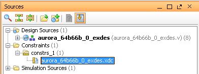
Adding a constraints file will require some modifications to make the constraints work in LabVIEW vs Vivado. A successful application of constraints in Vivado will not ensure that constraints are properly applied in LabVIEW. Be sure to monitor the Xilinx log generated by your LV FPGA project compilation to identify any unapplied constraints, and correct issues as they arise.
Refer to the User Manual for more information on using %ClipInstancePath% on constraints so the cells, pins, or blocks being constrained can be located by the Vivado compiler in the LV FPGA design flow.
Write a VHDL Wrapper Around IP Core
At this point, the core is ready to be integrated into a VHDL Wrapper, which will essentially become the Component Level IP (CLIP) for the 6591R/92R.
This process is not trivial, and requires a deep understanding of Digital Design knowledge and experience. It will also involve understanding the FPGA interface provided by the 6591R/92R and being able to appropriately interface those signals to the IP core and the wrapper.
Refer to a premade Sample Project to gain a better understanding of what is required in a CLIP.
Reference the User Manual for more details and assistance on this process.
Synthesize Full Project
When you have your .edf file and your .xdc files created, along with the source HDL integrated into a CLIP, you are now ready to move into the LabVIEW project to begin integrating your IP into the 6591R/92R. The last recommended step before you approach this point is to synthesize and debug your design here to make sure it is fully functioning.
A VHDL test bench is desirable in this scenario to test the functionality of the IP core and verify the wrapper is working properly. Xilinx provides example designs with simulation files that can be a starting point for creating your own test bench for your design.
Having a good understanding of the CLIP and the knowledge that it is working will help debug your design as you continue development in LV FPGA. That way, compiled bitfiles in LabVIEW that end up failing or causing issues can be debugged in LV FPGA with confidence.
Create LabVIEW Project
Open LabVIEW (latest supported release) and create a new project. You can right click My Computer and select New » Targets and Devices to add the 6591R/92R FPGA target to the project.
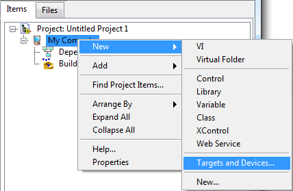
Reference the User Manual for more details and assistance on this process.
Add CLIP to Project
Once the target is configured, it is time to integrate your IP core in your VHDL wrapper (CLIP) into the LabVIEW project so that you can interface to the CLIP signals and compile designs based on your CLIP. Right click the FPGA Target and select Properties to open up a new configuration window.
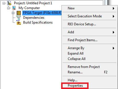
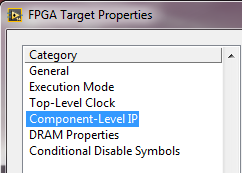
To add a CLIP to your project, select the Component-Level IP item under the left hand section and click the top right button to Create File, which will begin the CLIP Wizard. Follow the steps in the CLIP wizard to create your Socketed CLIP for the project.

The important note in this process is when you add source files to the CLIP, you will want to include your top level CLIP file, any referenced HDL files by your CLIP, your .edf netlists for your IP core, and your .xdc constraints file for the VHDL Wrapper top level. From the Aurora sample project:
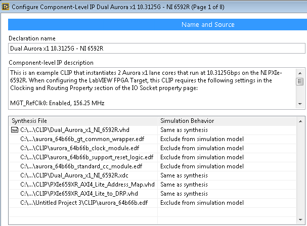
Reference the User Manual for more details and assistance on this process.
Successfully Compile LV FPGA Project
Assuming the CLIP synthesized correctly in Vivado, create a build specification in the LabVIEW project to start compilation of the CLIP + LV FPGA code associated with the target. If the constraints are done correctly, there are no timing violations in the design, and no other issues are present, you should end up with a completed bitfile for the 6591R/92R.
It will take some work on the LV FPGA side to bring data to the Host, and also to configure the CLIP and use standardized interfaces associated with the IP core. We provide many Instrument Design Libraries (IDL) that will assist you in building the interface from the CLIP to your Host.
Congratulations! You have taken IP from a 3rd party and configured, generated, and integrated this IP into a 6591R/92R application.