Locating Your Device Pinout
Before connecting any signals, locate your device pinout.
- Open NI Measurement & Automation Explorer (MAX) and expand Devices and Interfaces.
- Right-click on your device name and select Device Pinouts.
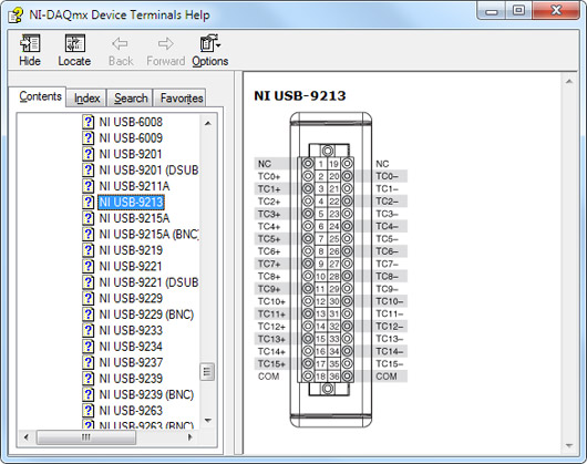
Figure 1. Device Terminals Help
The following terminal types correspond with thermocouple measurements:
- TC x (+/-): Most NI thermocouple hardware refers to TC+ and TC- terminals for each differential measurement channel.
- AI x (+/-): Some devices may refer to AIx+ and AIx- instead, where x refers to the channel number.
Connecting a Thermocouple to Your Device
The next step is to physically connect the thermocouple to your DAQ device.
- Click the Connection Diagram tab in NI MAX to continue.

Figure 2. Thermocouple Connection Diagram
Each thermocouple wire has a positive lead and a negative lead. The connection diagram in Figure 2 indicates which pins on your DAQ device should be wired according to the physical channel you selected. Connect the positive lead of the thermocouple to the TC+ terminal and the negative lead of the thermocouple to the TC– terminal. If you are unsure which of the thermocouple leads is positive and which is negative, check the thermocouple documentation or the thermocouple wire spool.
If you are using a shielded thermocouple, connect the COM terminal of your device to the shield and the shield to a common-mode voltage reference of the thermocouple. A common-mode voltage reference is a voltage that is within ±1.2 V of the common-mode voltage of the thermocouple. If you are using a floating thermocouple or a thermocouple within ±1.2 V of earth ground, connect COM and the shield to earth ground. The shield grounding methodology can vary depending on the application. Refer to Figure 3 for an illustration of a typical shielding configuration.
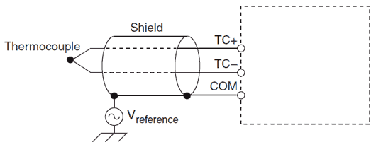
Figure 3. Connecting a Shielded Thermocouple
Configuring a Thermocouple Measurement
You can use NI MAX to quickly verify the accuracy of your measurement system setup. Using a NI-DAQmx Global Virtual Channel, you can configure a thermocouple measurement without any programming. A virtual channel is a concept of the NI-DAQmx driver architecture used to represent a collection of device property settings that can include a name, a physical channel, input terminal connections, the type of measurement or generation, and scaling information.
Follow these steps to begin:
- With NI MAX open, select Data Neighborhood and click Create New.
- Select NI-DAQmx Global Virtual Channel and click Next.
- Select Acquire Signals» Analog Input» Temperature» Thermocouple.
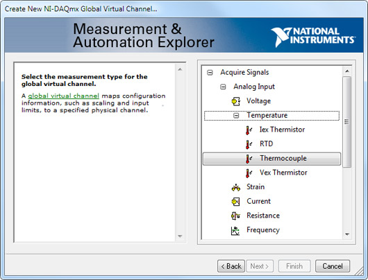
Figure 4. Creating an NI-DAQmx Virtual Channel
- Select ai0 or whichever physical channel you intend to connect to your thermocouple. A physical channel is a terminal or pin at which you can measure or generate an analog or digital signal. A single physical channel can include more than one terminal or pin, as in the case of a differential thermocouple input channel. In this case, ai0 corresponds to TC0+ and TC0- on the NI USB-9213 pinout diagram.
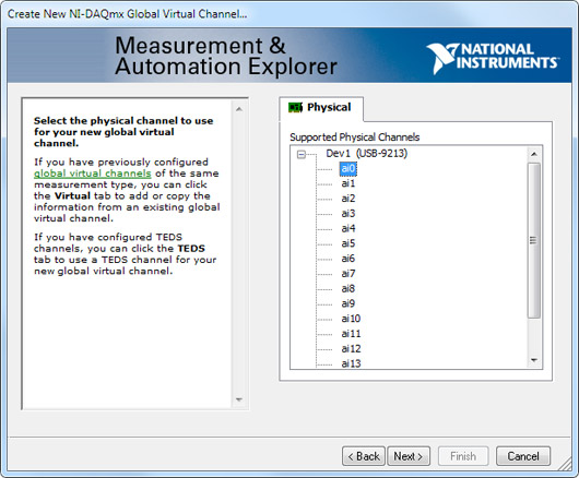
Figure 5. Device Physical Channels
- Click Next and enter a name for the global virtual channel or leave the default.
- Click Finish and you should see the following screen in NI MAX:
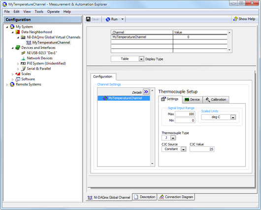
Figure 6. Setting Up a Thermocouple Channel in NI MAX
- On the settings tab, type in the minimum and maximum temperature values you expect to read from your thermocouple (0 to 100 °C by default).
- Select your thermocouple type and CJC Source and CJC Value.
Testing the Thermocouple Signal
With NI-DAQmx global virtual channels, you can preview your measurements.
- With NI MAX still open, click back on the NI-DAQmx Global Virtual Channel tab and click on the Run button. You see the temperature value of your thermocouple displayed at the top of the screen.
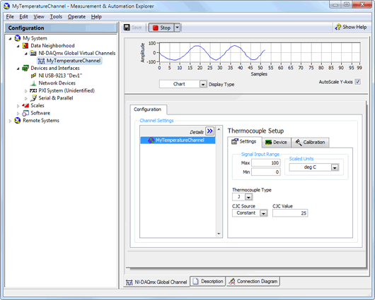
Figure 7. Previewing a Thermocouple Measurement in NI MAX
You can choose to view the signal in tabular form or as a graph by selecting Graph from the
Display Type pull-down menu. You also have the option of saving your NI-DAQmx Global Virtual Channel should you wish to refer to this configuration screen again in the future.
LabVIEW Example for Thermocouples
The following example code is provided in the LabVIEW Example Finder under Hardware Input and Output» DAQmx» Analog Input» Thermocouple - SW-Timed Input. vi. (Note that this example file may have a different name or filepath depending on your LabVIEW version.)
The front panel of this example allows the user to:
- Select the physical channel(s) of the device from which the thermocouple data will be taken.
- Set the maximum and minimum temperature range.
- Select the thermocouple type from a list of supported types.
- Choose the physical units to scale the data.
- Select a source, channel, and value for cold-junction compensation (CJC).
- Configure the autozero mode.
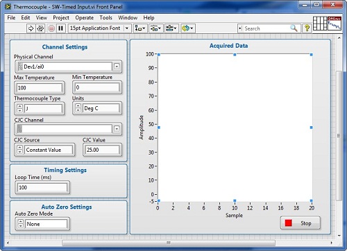
Figure 8. Thermocouple Example Front Panel