Starting a New CompactRIO Project in LabVIEW
Begin by creating a new project in LabVIEW, where you will manage your code and hardware resources.
- Create a new project in LabVIEW by selecting File » New Project
- Adding your CompactRIO system to the project by right-clicking on the Project item at the top of the tree and select New » Targets and Devices… This dialog allows you to discover systems on your network or add offline systems.
Figure 1. Add new targets and devices to your LabVIEW project
- Expand the Real-Time CompactRIO folder and select your system. Click OK to close the dialog window.
Note If your system is not listed, LabVIEW could not detect it on the network. Ensure that your system is properly configured with a valid IP address in Measurement & Automation Explorer. If your system is on a remote subnet, you can also select to manually enter the IP address.
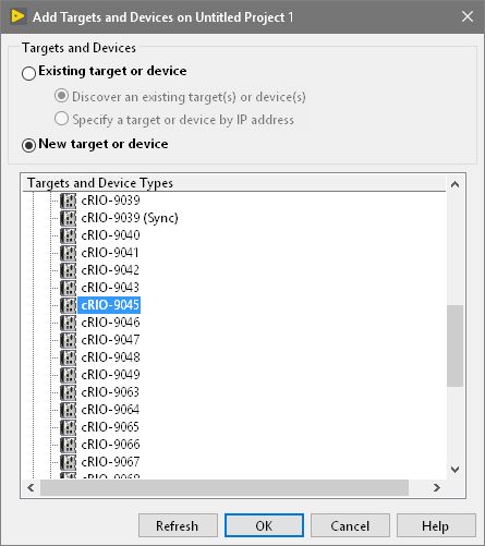
Figure 2. Select a new CompactRIO system
Select the Appropriate Programming Mode
CompactRIO systems have at least two user-selectable modes. Some models of the CompactRIO have an additional user-selectable mode to program in Real-Time NI-DAQmx. Please refer to this article to determine if your CompactRIO is capable of using Real-Time NI-DAQmx. After adding your target to the project, you will be prompted to select which programming mode you would like to use.
Note: You can change the programming mode later if needed using the CompactRIO Chassis Properties dialog box.
Real-Time (NI-DAQmx) Mode – CompactRIO with NI-DAQmx is the latest addition to the CompactRIO Controller family. It brings two software experiences into one by combining the ease of use of NI-DAQmx and the low-level functionality of LabVIEW FPGA. It also simplifies system architectures by bringing the latest in synchronization and control technologies to the CompactRIO platform. To program a C Series Module in this mode, place it under the Real-Time Resources folder in the LabVIEW project.
Real-Time Scan (I/O Variable) Mode – this option allows you to program the real-time processor of your CompactRIO System, but not the FPGA. In this mode, NI provides a pre-defined personality for the FPGA that periodically scans the I/O and places it in a memory map, making it available to LabVIEW Real-Time. CompactRIO Real-Time Scan Mode is sufficient for applications that require single-point access to I/O at rates of a few hundred hertz. To program a C Series Module in this mode, place it under the Real-Time Scan Resources folder in the LabVIEW project. To learn more about scan mode, read Understanding NI CompactRIO Scan Mode and view the benchmarks.
Note: NI recommends Real-Time (NI-DAQmx) Mode over Real-Time Scan (I/O Variable) Mode.
LabVIEW FPGA Interface Mode – This option allows you to unlock the real power of CompactRIO by customizing the FPGA personality in addition to programming the real-time processor, achieving performance that would typically require custom hardware. Using LabVIEW FPGA, you can implement custom timing and triggering, off-load signal processing and analysis, create custom protocols, and access I/O at its maximum rate. To program a C Series Module in this mode, place it under the FPGA target in the LabVIEW project.
LabVIEW will now attempt to detect the chassis and C Series I/O Modules present in your system and automatically add them to the LabVIEW Project.
Note: If your system was not discovered and you choose to add it offline, you will need to add the chassis and C Series I/O manually. This document discusses this process for scan mode and FPGA mode.
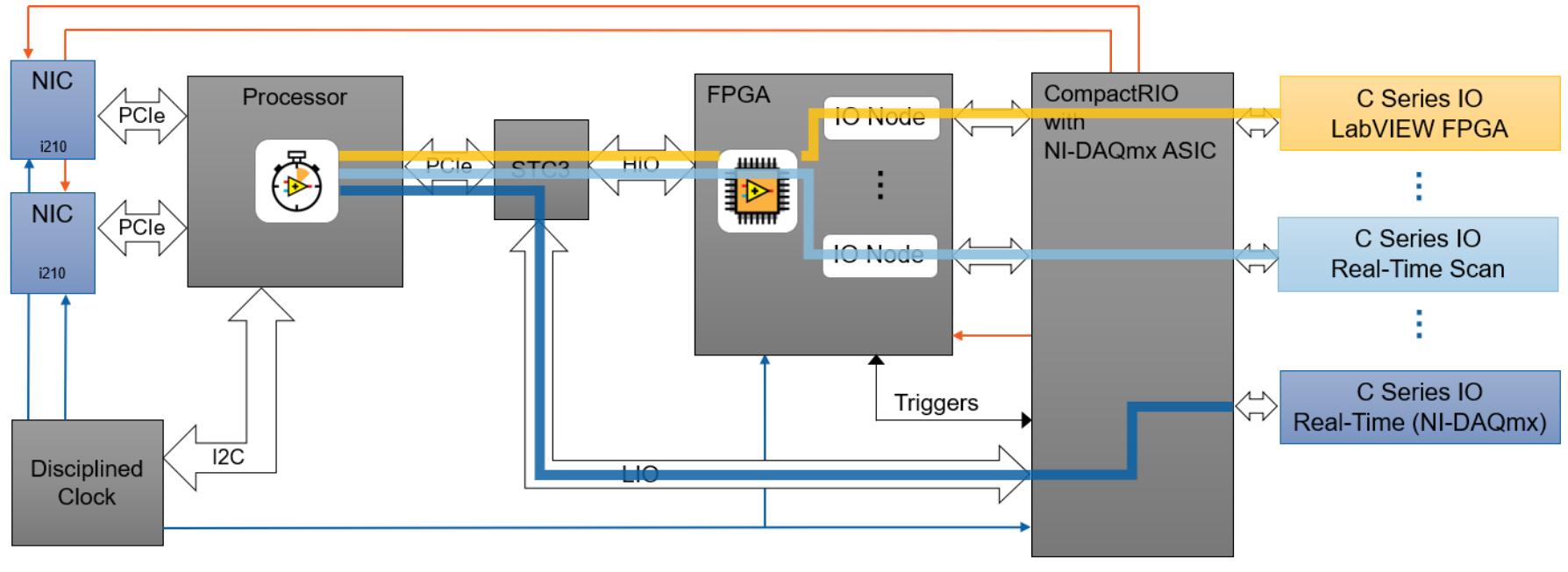
The figure below shows how each mode sends the I/O data through a unique path. For Real-Time (NI-DAQmx) mode, the data is read through the processor via NI-DAQmx VI’s. For Real-Time Scan (IO Variable) mode, the data is sent through the FPGA but is ultimately accessed on the processor by dragging and dropping IO Nodes to the Real-Time VI. For LabVIEW FPGA mode, the I/O is read directly from within the FPGA by dragging and dropping IO Nodes to the FPGA VI.
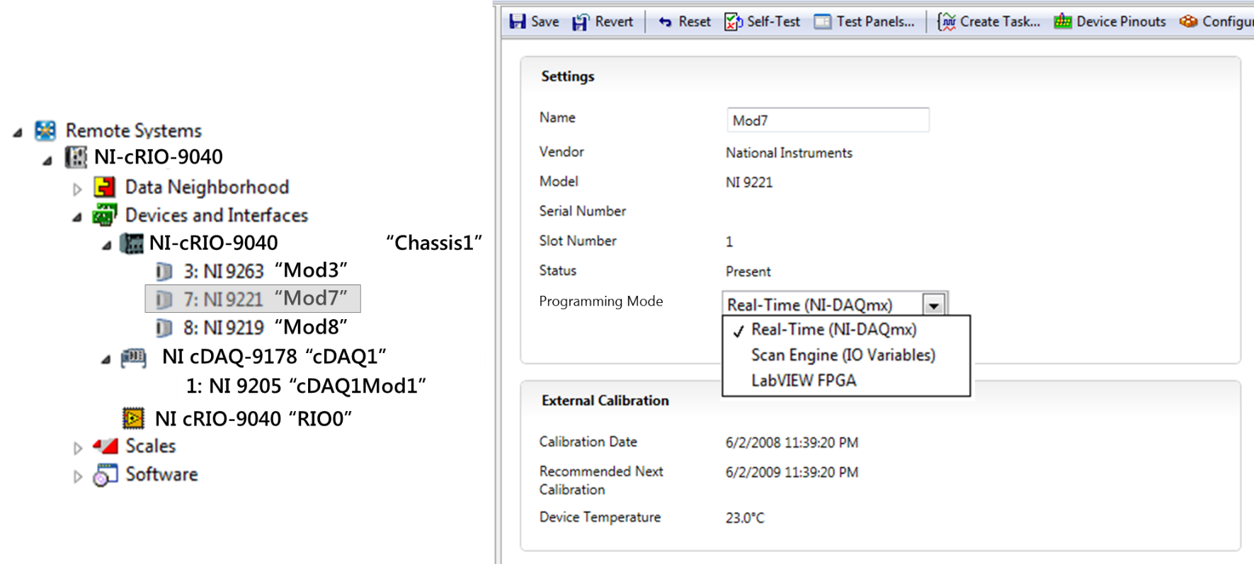
If you have LabVIEW Real-Time, LabVIEW FPGA, and NI-DAQmx on your development computer, you can select which programming model to use on a per-module basis by placing the module under the appropriate heading in the project. The programming mode is indicated by the text next to the module in the LabVIEW project. You can also select which programming model to use by selecting from the drop-down menu in Measurement and Automation Explorer (MAX).
Create a basic logging application on the CompactRIO
This section is broken into three subsections that show you how to create a basic temperature logging application. Please select a section based on your desired programming mode and your CompactRIO controller. Please refer to the Select the Appropriate Programming Mode section if you are unsure which programming mode you desire. The sections are listed in the following order
- NI-DAQmx API
- FPGA Programming Mode
- Real-Time Scan Mode
I. Using NI-DAQmx API
The NI-DAQmx driver comes with a variety of example VIs to help users gain familiarity with the NI-DAQmx API. This section will instruct you on how to import a NI-DAQmx Example onto a CompactRIO target. We will be importing the Thermocouple - Continuous Input VI.
- Create a new project in LabVIEW by selecting File » New Project
- To add your CompactRIO system to the project, right-click on the Project item at the top of the tree and select New » Targets and Devices…
Figure 3. Creating a new Target in the LabVIEW project
- This dialog allows you to discover systems on your network or add offline systems. Expand the Real-Time CompactRIO folder, select your cRIO-904x system, and click OK. Note: If your system is not listed, LabVIEW could not detect it on the network. Ensure that your system is properly configured with a valid IP address in Measurement & Automation Explorer. If your system is on a remote subnet, you can also select to manually enter the IP address.
Figure 4. Searching for a Real-Time CompactRIO in LabVIEW
- To add the Thermocouple - Continuous Input.vi the LabVIEW project, right-click the cRIO-904x target and select Add>> File... which will open the file explorer.
NI-DAQmx examples will install by default to and can be found here:
C:\Program Files (x86)\National Instruments\LabVIEW <xxxx>\examples\DAQmx
(on x32 OS the default file path will be C:\Program Files\National Instruments\LabVIEW <xxxx>\examples\DAQmx).
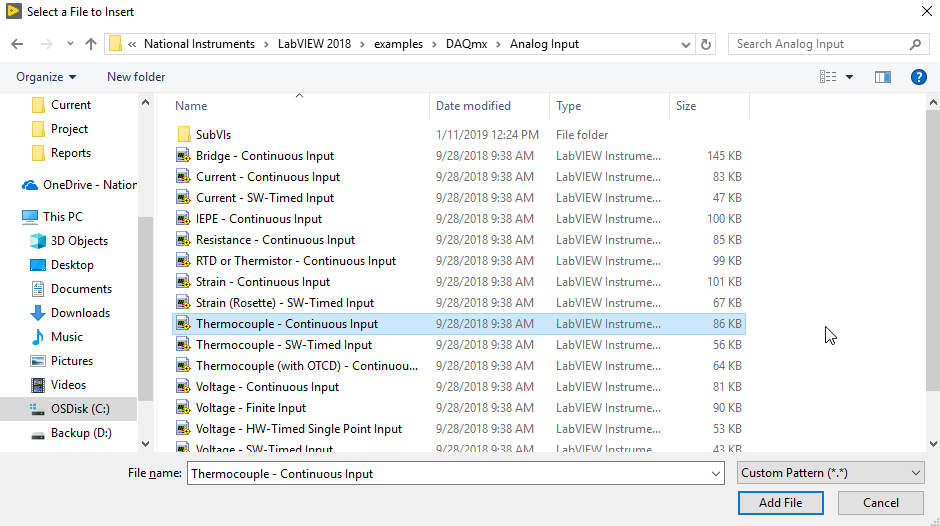
Figure 5. File location of the Thermocouple - Continuous Input VI
- Ensure that the modules configured to be used in the NI-DAQmx task of the Thermocouple - Continuous Input.vi are in Real-Time (NI-DAQmx) mode by moving them under the Real-Time Resources project item. Also, ensure that any changes in programming mode are deployed to the target.
Figure 6. Hierarchy of the LabVIEW project
- Open the VI and configure your physical channel controls/ constants for the appropriate module and channels. Note: The NI-9211 requires a lower sample rate than the default values observed in this example VI.
- Open the block diagram. Navigate to the Timing Settings section of the block diagram.
- Implement a DAQmx Configure Logging (TDMS) VI between the DAQmx Timing Property Node and the Case Structure. Ensure you have the task and error wires going through the DAQmx Configure Logging (TDMS) VI.
- Right-click the logging mode terminal and select Create >> Constant. Ensure the constant is set to Log and Read.
- Right-click the file path terminal and select Create >> Constant. Refer to step 23 of the Using the CompactRIO Real-Time Scan Mode section for instructions on how to reference your file path.
- Verify that your configuration of the DAQmx Configure Logging (TDMS) VI appears as seen below.
Figure 7. Required edits to the example VI
- Navigate to the front panel and run the application.
- Click the STOP button when you have finished viewing and logging data. You can download the solution from the Downloads/Attachment section of this document.
II. Using LabVIEW FPGA Interface ModeThe LabVIEW FPGA Interface Mode is capable of utilizing the CompactRIO's onboard FPGA to increase performance and determinism. An example project is available from the shipped examples, found at C:\Program Files (x86)\National Instruments\<LabVIEW Version>\examples\CompactRIO\Module Specific\NI 9205\NI 9205 Basic IO\NI 9205 Basic IO.lvproj. This project shows how to read analog input channels from an NI 9205 module. It was created using an NI 9205 module in slot 1 of a cRIO-9101 backplane. The project consists of two VIs as seen below.
Figure 8. Example hierarchy of the LabVIEW project
The
NI 9205 Basic IO (FPGA) VI communicates with the
NI 9205 Basic IO (Host) VI using a DMA FIFO as seen in the below block diagram. The VI running on the Real-Time processor will need to read the values out of the DMA FIFO. Please refer to the example project to help understand the methods the
NI 9205 Basic IO (Host) VI uses to read and store the temperature values received from the onboard FPGA.
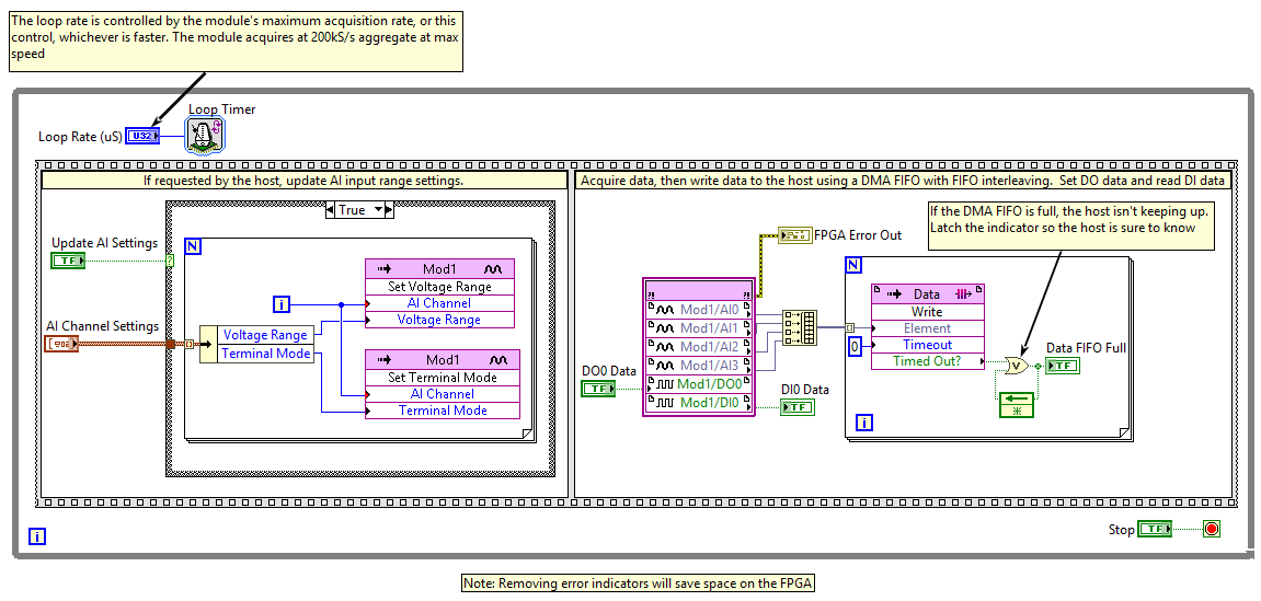 Figure 9
. Block Diagram of the
NI 9205 Basic IO (FPGA) VIThis section will walk you through creating a basic logging application on CompactRIO using scan mode. You should now have a new LabVIEW Project that contains your CompactRIO system, including the controller, chassis, and C Series I/O Modules. In this tutorial we will be using an NI 9211 Thermocouple input module; however, the process can be followed for any analog input module. You can also download the solution from the Downloads/Attachments section of this page.
Note: NI recommends Real-Time (NI-DAQmx) Mode over Real-Time Scan (I/O Variable) Mode.
- Save the project by selecting File»Save in the top left corner.
- Enter the name as Basic logging with scan mode and click OK to close the dialog window.
Figure 10. Save LabVIEW Project Basic logging with scan mode
- Create a VI by right-clicking on the CompactRIO Controller in the project and selecting New»VI. Save the VI as RT.vi. This project will only contain one VI, which is the LabVIEW Real-Time application that runs on the CompactRIO Controller.
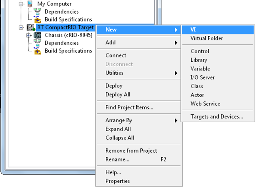
Figure 11. Create a new VI underneath the recently added CompactRIO Controller
- Place a flat sequence structure with three frames on your RT.vi block diagram as shown below. The basic operation of this application will include three routines: startup, run, and shutdown. A flat sequence structure is an easy way to enforce this order of operation.
Figure 12. Flat Sequence structure in LabVIEW
- Add a timed loop to the Run frame of the sequence structure. Timed loops provide the ability to synchronize code to various time basis, including the NI Scan Engine that reads and writes scan mode I/O.
Figure 13. Flat Sequence structure in LabVIEW with Timed Loop
- Double-click on the clock icon on the left input node to configure the timed loop.
Figure 14. Open Timed Loop configuration by double-clicking on the top left corner
- Select Synchronize to Scan Engine as the Loop Timing Source.
- Click OK. This will cause the code in the timed loop to execute once, immediately after each I/O scan, ensuring that any I/O values used in this timed loop are the most recent values.
Figure 15. Configure Timed Loop using Scan Engine as a Timing Source
- Right-click the CompactRIO controller in the LabVIEW project and select Properties.
- Select Scan Engine from the categories on the left and enter 100ms as the Scan Period. This will cause all the I/O in the CompactRIO system to be updated every 100ms (10Hz). The Network Publishing Period can also be set from this page, which controls how often the I/O values are published to the network for remote monitoring and debugging. Click OK.
Figure 16: Adjust the Scan Period to control the refresh rate
- Select all the channels below the module by clicking on them and using the shift key, then drag and drop them into the timed loop on your RT.vi diagram as shown below. When using CompactRIO Scan Mode, you can simply drag and drop the I/O variables from the LabVIEW Project to the block diagram. Expand the CompactRIO Controller, chassis, and the I/O module you would like to log.
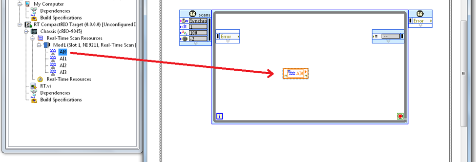
Figure 17. Drag and Drop C Series I/Os into the Timed Loop
Tip: Use the
Align Objects » Left Edges and
Distribute Objects » Vertical Compress items on the LabVIEW toolbar to organize the I/O variables on your diagram.
Figure 18. Align Objects using Left Edges and Vertical Compress
You can modify the module properties by double-clicking it as shown below:
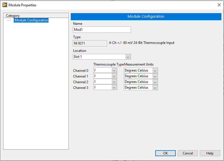
Figure 19. Setting module properties
- Place a normal while loop in the Run frame under the timed loop, which will be used for the file I/O task. Because file I/O takes an undermined amount of time, you must separate the I/O acquisition task and the file I/O task. Neglecting this requirement could lead to losing data, since the file I/O may take longer than the I/O scan, causing a sample to be missed.
In order to write the data to disk in the regular while loop, you need to transfer the I/O values from the timed loop using a real-time FIFO. This will provide a buffer between the two loops. The timed loop will run, synchronized the I/O scan, and write the new I/O values to the buffer each time. Then, the regular while loop will read the data out of the buffer and write it to disk. Separating the I/O task and disk access in this way allows your timed loop to run with “real-time” performance, meaning that it will always finish on time.
Figure 20. Using to loops to make sure logging data doesn't slow down I/O sampling rate
Figure 21. Real-Time Task accessing I/Os vs. Low priority task logging data
- In the LabVIEW Project, right-click on the CompactRIO Controller and select New»Variable.
Figure 22. Adding new Variable in the LabVIEW project
- Name the variable Data buffer, select Single Process as the Variable Type.
- Select Array of Double as the Data Type. This will create a locally scoped variable (no network publishing) that contains an array of double-precision floating-point numbers.
Figure 23. Using Variable Properties to define Variable and Data Types
- Then select RT FIFO from the menu on the left.
- With the RT FIFO category selected, select the Enable RT FIFO check box, select Multi-element for the FIFO Type.
- Enter 50 for the Number of arrays, and enter 4 for the Number of elements (if you are logging a number of channels other than 4, enter that instead.) This configures the variable to operate as a real-time-safe FIFO, which can serve as the data buffer between our real-time and low priority tasks. The FIFO will hold 51 dimensional arrays, each of which contains four double-precision numbers. Click OK.
Figure 24. Using Variable Properties to enable RT FIFO
- Drag and drop the Data buffer RT FIFO into your timed loop and use a Build Array function to build an array from the I/O variables and pass it into the RT FIFO.
Figure 25. Drag and drop the Data buffer and place it in the timed loop
- Drag and drop an additional copy of the Data buffer RT FIFO into the regular while loop, where you will read the data out and log it to disk.
- Right-click on the RT FIFO and select Show Timeout and wire a timeout of 100. This will cause the RT FIFO to wait up to 100ms for new data to arrive in the buffer before it times out. If data is present in the buffer, the RT FIFO will return the oldest data in the buffer immediately.
Figure 26. Drag and drop an additional copy of the Data buffer
- Place a TDMS Open VI in the Startup frame of your sequence structure.
- Create constants for the file path and operation inputs. Type c:\tempdata.tdms in for the file path and select create or replace for the operation. In case your CompactRIO Controller is running a different Real-Time OS choose the appropriate file path shown below. Please see Real-Time Controllers and Real-Time Operating Systems Compatibility for more information.
 Figure 26
. Using the right file path depending on the CompactRIO Controller that is used
- Re-create or drag and drop the VI snippet below from your web browser to your diagram to perform the file I/O.
- Place this code in the regular while loop and wire it as shown below. A case structure is used to execute this section of code only when the RT FIFO does not time out, indicating that new data has been returned from the buffer. Then, the data is formatted to be written to the TDMS file and displayed on the waveform chart. A stop button for the while loop is also provided in addition to checking for errors as a stop condition.
Note: This image is a LabVIEW snippet, which includes LabVIEW code that you can reuse in your project. To use a snippet, right-click the image, save it to your computer, and drag the file onto your LabVIEW diagram.
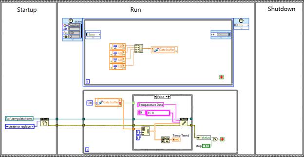 Figure 27.
 Logging Code without a Shutdown
- In the LabVIEW Project, create another shared variable by right-clicking on the existing library that was created automatically and contains the Data buffer variable and selecting New»Variable.
- Name the variable stop, select Single Process, and select Boolean. Select the RT FIFO category on the left.
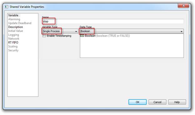 Figure 28.
 Select Single Process and use Boolean as a Data Type
- Select Enable RT FIFO, leave Single-element selected and click OK. This creates a variable that is safe to read from in tasks that require real-time performance.
- Place a copy of the stop variable in the timed loop and wire it to the stop condition.
- Place another copy of the stop variable in the regular while loop and write the result of the OR function to it as shown. This will cause the timed loop to stop when the regular while loop stops.
- Place a TDMS Close function in the Shutdown frame and wire the file reference and error cluster through to it. Also, create and indicator from the TDMS Close error out terminal. Your completed application should look like the image below:
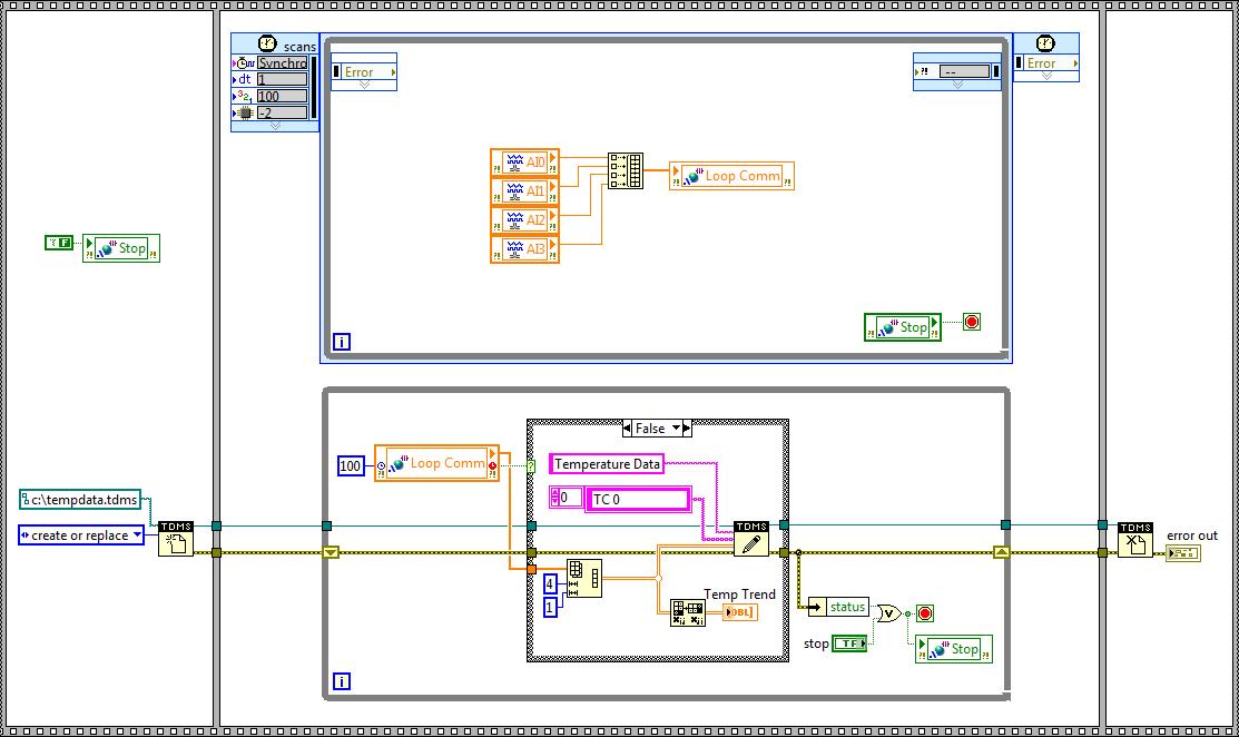
Figure 29. Finished LabVIEW Block Diagram
- Click Run on RT.vi, click Save for any unsaved items, and click OK on any dialogs or warnings about applying changes to the CompactRIO system. LabVIEW will now deploy your VI over Ethernet to run embedded on the CompactRIO system.
- Once the VI deploys and begins running, view the front panel of your VI to see the current I/O values plotted on the waveform chart.
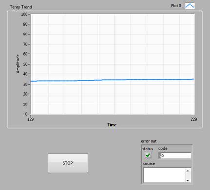 Figure 30
. Finished LabVIEW Front Panel showing logging data
- Click STOP once you are finished viewing and logging data.
Congratulations! You have successfully created an embedded logging application with LabVIEW and CompactRIO. To continue learning, check out the additional resources on the
Getting Started with CompactRIO Hardware and LabVIEW page.
Accessing the logged data
Complete these steps to retrieve and view the data logged on the CompactRIO system. If you don't have an FTP server installed on your system, CompactRIO also supports WebDAV (Web Distributed Authoring and Versioning). It’s a secure alternative to exchange files using a standard web browser. Please see
Using WebDAV to Transfer Files to and from your Real-Time Target for more information.
- Using Windows Explorer or a Web browser, navigate to ftp:// <ip address> where <ip address> is the IP address of your CompactRIO system.
- Download tempdata.tdms (or whatever you named the TDMS file)
- If you have Microsoft Excel, you can view TDMS files by selecting the Add-Ins tab and clicking the TDM Importer. The first page of the workbook contains file information and the remaining sheets contain the channel data. The TDM Importer installs with LabVIEW by default; however, if the TDM Importer is not present, you can install it from here.
 Figure 31
. Install TDM Importer in order to open the TDMS files directly in Excel
- If you do not have Excel, you can view the TDMS file using the TDMS File Viewer VI in LabVIEW.