Creating a Modbus Master I/O Server
In this section, you will create a LabVIEW interface to the Modbus addresses called an I/O Server. The I/O Server automatically updates LabVIEW with the current values.
- In the Getting Started window of LabVIEW, click File»New Project. This opens a new LabVIEW Project.
- If the Context Help window is not visible, press Ctrl+H to display the window. Keep this window open for helpful information about items under your cursor.
- In the LabVIEW Project window, right-click My Computer and select New»I/O Server, as shown in Figure 1.
Figure 1: Creating a New I/O Server through the LabVIEW Project
- Select Modbus in the Create New I/O Server Window and click Continue.
- Select Modbus Ethernet from the Model drop down menu.
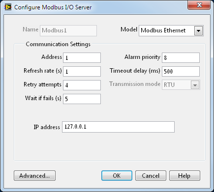
Figure 2: Configuring Modbus Master I/O Server
- Enter the IP Address of your target Modbus Slave in the IP address field. If you don’t know how to determine a computer’s IP address refer this web page: External Link: How to Find IP Information. In this example we are running the Modbus Slave on the same computer as the master, so we use the localhost IP address, 127.0.0.1.
- Select OK. A library is automatically created in your Project Explorer window to manage the I/O Server.
- Save the project as ModbusDemoProject and the library as ModbusDemoLibrary by selecting File»Save All from the project explorer window.
Bind Shared Variables to Modbus Addresses Through the I/O Server
In this section, you will learn to create shared variables bound to the Modbus addresses, giving you native access in LabVIEW to PLC data. With the shared variable you can share data across LabVIEW applications on a single computer or across the network.
- Create new shared variables that are bound to the Modbus addresses.
- Right-click the newly created ModbusDemoLibrary and select Create Bound Variables…
- In the Create Bound Variables window, expand the tree down to the Modbus1 in order to select the desired address range.
- Then select 000001-065535, and click on Add Range. Leave the default of Data Item as 000001 and Number of items as 1. Hit OK.
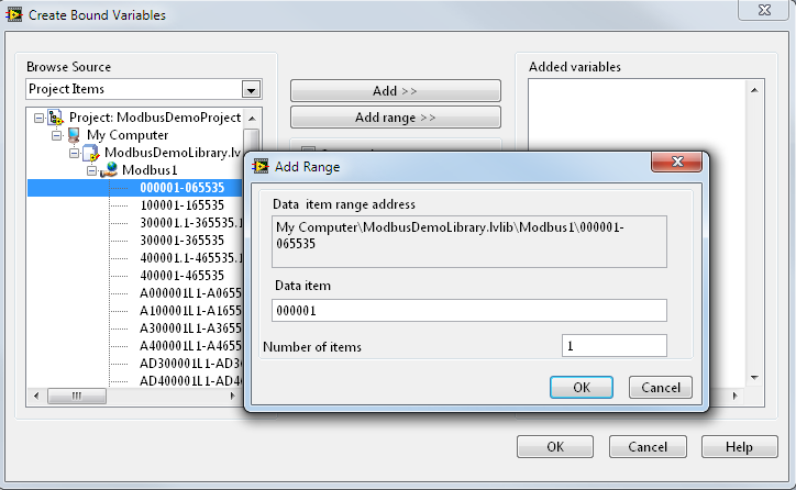
Figure 3: Select Modbus Addresses to Bind to Shared Variables
- Your configuration window should now have variable 000001 in the Added variables section.
- Click OK. This creates a shared variable that is bound to the Modbus address and loads it into the Multiple Variable Editor.
- In the Multiple Variable Editor, select Done. This adds the new shared variables to the library that was created earlier.
- In the Project Explorer right click on 000001 and select Rename. Rename the variable to Coil1.
Note: The LabVIEW DSC Module enhances shared variables by adding the ability to log data, alarms, and events directly to a database without ever writing a LabVIEW application.
- Deploy the shared variables by right-clicking on ModbusDemoLibrary and selecting Deploy All. This publishes the shared variables, making them available on the network to other computers.
You now have access to Modbus data natively in LabVIEW through the shared variables
Writing to Modbus Addresses in LabVIEW
- From the Project Explorer, right-click My Computer and select New»VI. This creates a new virtual instrument or VI. A VI is used to create a user interface and executable graphical code.
- By default, you see the Front Panel, which is the user interface of the VI. LabVIEW has many built-in UI components, such as graphs, charts, dials, and so on, which you can use to build a powerful, intuitive UI. Select View»Controls Palette or right-click anywhere on the Front Panel to bring up the Controls palette. Mouse over the various categories to explore the UI components in LabVIEW.
- Select a push button from the Controls palette by selecting Express»Button & Switches»Push Button, and place it on the Front Panel, as shown in Figure 4 and 5.
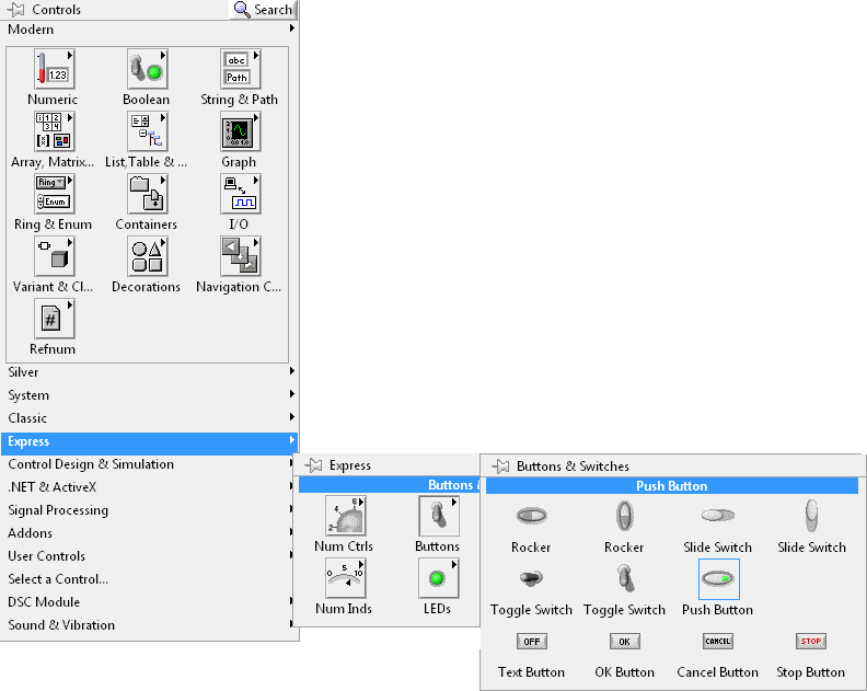
Figure 4: Select a Push Button from the Controls Palette
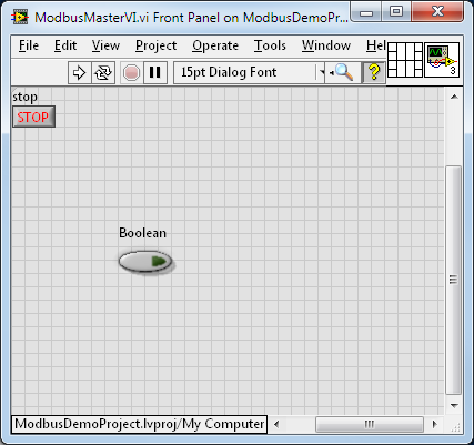
Figure 5: Push Button Placed on the Front Panel
- In the VI, select Window»Show Block Diagram or press Ctrl+E to show the Block Diagram. The Block Diagram is where you build the behavior of your application. Notice the icon on the Block Diagram, which represents the push button on the Front Panel. By pressing the push button on the front panel, you change the Boolean value passed out of the icon terminal on the block diagram.
- In the Project Explorer, expand the ModbusDemoLibrary library and select the Coil1 shared variable.
- Drag and drop the Coil1 Shared Variable from the Project Explorer to the Block Diagram of the VI. The shared variable acts as a source of data to other terminals on the Block Diagram.
- Right click on your newly placed Coil1 Shared Variable and select Access Mode»Write. This allows you to write to instead of read from the Shared Variable
- Use the Connect Wire tool to wire the Coil1 shared variable to the Boolean push button by clicking on the Coil1 shared variable and then on the Boolean push button, as shown in Figure 6.
Figure 6: Wiring Block Diagram Items Together
Now data flows from the Boolean push button to the shared variable when the VI is running.
- Open the Functions palette by selecting View»Functions Palette or right-clicking anywhere on the Block Diagram. The Functions palette contains hundreds of analysis functions, control functions, and structures for graphical programming.
- Select a while loop from the Functions palette by navigating to Programming»Structures»While Loop. Once you select the while loop, your cursor appears as shown in Figure 7. This allows you to wrap a while loop around a section of code.
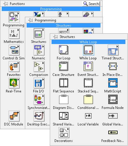
Figure 7: Selecting a While Loop

Figure 8: While Loop Cursor
- Using the while loop cursor, place a while loop around the shared variable and waveform chart by clicking and dragging the cursor. Now create a Stop control in while loop by right-clicking on the Loop Condition and selecting Create Control. This places a Stop button on your Front Panel which allows the user to stop the VI.
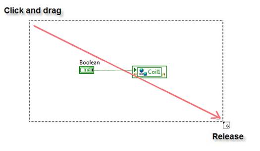
Figure 9: Placing a While Loop around the Shared Variable and Control
The while loop causes the code within it to execute continuously until stopped by the user or additional logic in the VI.
- As the while loop is now, it will run as fast as possible. A Wait Until Next ms Multiple VI should be added to the loop so that the loop will execute every set amount of seconds, in this case 100ms.
Figure 10: Adding timing to the While Loop
- Return to the Front Panel by selecting Window»Show Front Panel or pressing Ctrl+E.
- Click the Run button on the tool bar to execute the VI.

Figure 11: Run Button
- Click Close on the Deploy… window once the deployment completes. When the application begins executing, you can now toggle the push button true and false. This will update the Modbus bound Shared Variable in the Shared Variable engine with True or False
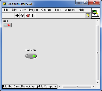
Figure 12: Completed Front Panel - Controlling a Modbus Coil
- Congratulations! You successfully accessed PLC data in your LabVIEW application, so you can incorporate powerful analysis and control functions in your solution.
Viewing Shared Variables with Distributed System Manager
- From the Project Explorer window, select Tools»Distributed System Manager. This opens a window that you can use to manage your shared variables in various ways (view, deploy, undeploy, etc.).
- In the Tree pane of the Variable Manager, expand the localhost item under the My Systems category. Locate and expand the ModbusDemoLibrary library, and select Coil1 to display Auto View on the right hand side of the window
- You can now toggle the Boolean push button your front panel and see the result in Distributed System Manager like in Figure 13.
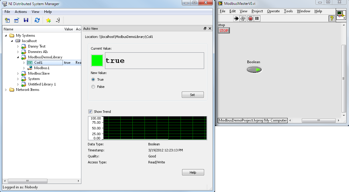
Figure 13: Viewing Coil1's value in Distributed System Manager
Note: The Distributed System Manager began shipping with LabVIEW 8.6. Previous versions of LabVIEW did this by going to Tools»Shared Variable»Variable Manager and dragging the shared variables into the Watched Variables: window.
Viewing the Coil Value With a Modbus Slave
In the first section of the document we created a Modbus Master that writes a Boolean value to a Modbus coil. This coil value is being stored in a Shared Variable that we then were able to see in the Distributed System Manager. In this next section we will show how a Modbus Slave can read the coil value that the Master is updating. The Modbus Master we created in part one is looking for a Modbus Slave at IP address 127.0.0.1 (localhost). So we need to create a Modbus slave on your local machine if we want to talk via Modbus to our Modbus Master.
- In LabVIEW open the NI Example Finder by clicking on Help»Find Examples.
- In the NI Example Finder browse to Toolkits and Modules» Datalogging and Supervisory Control» I/O Servers double click on Modbus Simulator.lvproj. See Figure 16.
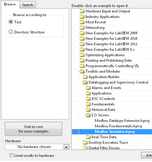
Figure 14: Modus Simulator in NI Example Finder
- Open the ModbusSimulator.vi from the project and then run it.
- Run your Modbus Master VI if it is not currently running. When the two are running you can see the Digital 1 LED on the Modbus Simulator light up, like figure 15.
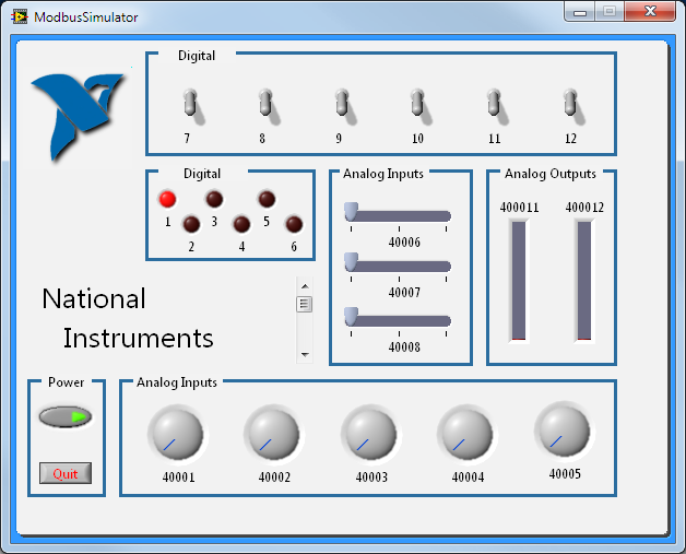
Figure 15: Modbus Simulator running and displaying Coil1's true value
- Click Quit on the Modbus Simulator, and then press Ctrl+E to switch to the block diagram.
- On the block diagram notice that Modbus address 000001 is being read with a Shared Variable. This Shared Variable is connected to the Modbus Master’s Coil1 value.
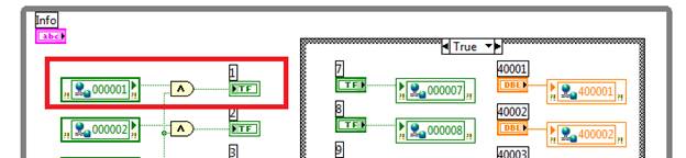
Figure 16: Modbus Simulator Block Diagram
Extra Challenge
To improve your understanding of the relationship between Modbus Masters and Slaves, a useful challenge would be modifying your Modbus Master program to read and control the rest of the values in the Modbus Simulator. You will need to add bound Shared Variables to the Modbus I/O Server in the ModDemoProject.