In order to generate a signal, we need to use Basic Function Generator VI which takes as inputs the type of waveform, number of samples, phase in, and the frequency of the waveform to be generated in Hz.
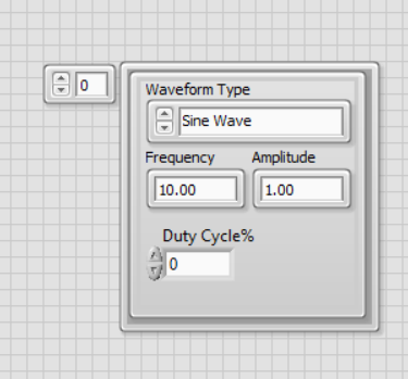
1. Create a cluster with 3 numerics and an unsigned word, which describe Waveform Type (Sine Wave, Sawtooth Wave, Square Wave, Triangle Wave), frequency, amplitude and duty cycle.
For this particular example, we will discuss only Square Wave Generation.
2. Develop a VI as shown in the picture below.

3. Configure the DAQmx VIs and run the VI.
After running the VI, we have a possibility to generate square wave and change the configuration like frequency, duty cycle and amplitude.