1. Download
NI-SCOPE that compatible with your LabVIEW version and Hardware. The reason to download NI-SCOPE because to configure the input coupling, we may need to use
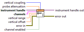
niScope Configure Vertical.vi, for you reference please refer to below photo:
2. Once completed the installation of NI-SCOPE, kindly please reboot your PC.
3. Open LabVIEW and create New VI and go to block diagram by press
Ctrl+E4. Open a session to the oscilloscope, by
right-click on the block diagram and go to
Measurement I/O > NI-SCOPE > Initialize.
5. Insert
niScope Configure Vertical.vi, by
right-click on the block diagram and go to
Measurement I/O > NI-SCOPE > Vertical.6. Create
control from vertical coupling of
niScope Configure Vertical.vi, with this control you can select whether to measure AC or DC.
7. Configure the vertical parameters such as input range and offset. For more information regarding channel names, refer to Channel String Syntax in the NI High-Speed Digitizers Help.
8. Insert Configure the horizontal parameters such as sampling rate and number of samples.
9. Insert
niScope Configure Horizontal Timing.vi, by
right-click on the block diagram and go to
Measurement I/O > NI-SCOPE > Horizontal. Configure an analog reference trigger on channel 0.
10. Insert
niScope Configure Trigger Edge.vi, by
right-click on the block diagram and go to
Measurement I/O > NI-SCOPE > Trigger. Configure the width of the samples that will be stored in the onboard memory of the device. This will save memory space and improve fetching speed at the cost of losing resolution. Only some devices support setting this width to a lower value than the native width.
11. Initiate the acquisition.
12. Fetch the data in binary format. Select between 8-, 16- or 32-bit size samples. The samples returned will be of the actual size stored.
13. Plot the binary data.
14. Check for errors and stop if any occurred.
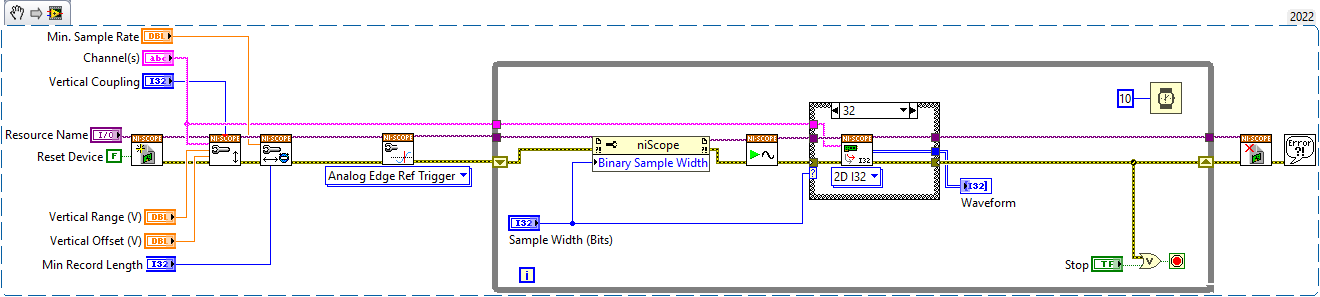
To have better understanding on wiring and connection you may need refer to below example VI: