Measure RF Interference Signal Power
- Record the VSA noise floor
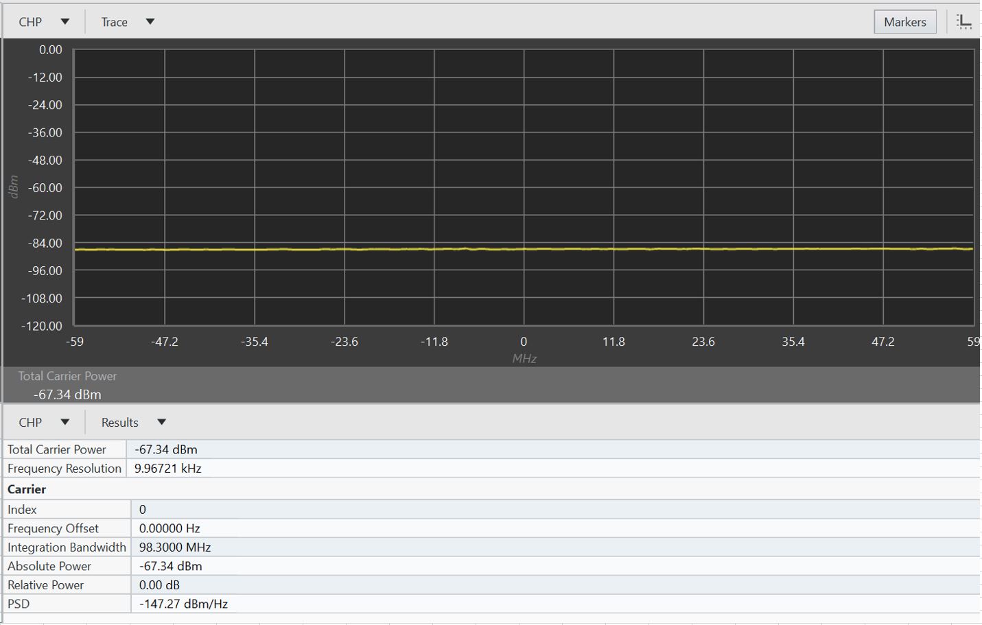
To measure the RF interference signal power, we need to measure and record the VSA noise floor before input simulated RF interference signal from VSG to VSA. Best practice is to connect a dummy load at VSA input port. In this article, as an example, the measured VSA noise floor
CPSA_noise is -67.34dBm in 98.3MHz bandwidth. Refer to below screen shoot for the measure noise floor:
- Generate the simulated RF interference signal from VSG with below configurations:
- Center frequency: 3.5GHz
- Bandwidth: 98.3MHz
- Power setting at VSG: -70dBm
- Jumper cable loss: 1dB estimated
- Power input to VSA: -71dBm
- Read the displayed power of -65.81dBm in VSA, shown below:
- Calculate the simulated RF interference power level (CPinterf_measured) with the formula discussed in overview section
CPinterf_measured = 10 x Log (10(-65.81/ 10) - 10(67.34/ 10) ) = -71.08dBm which is very close to the actual input power of -71.00dBm.
- Calculate more simulated RF interference power levels (CPinterf_measured) for other displayed power values (CPSA_display)
- Apply the formula shown in overview section and refer to table below for more values of calculated RF interference power
- Noticed the last row of the table, the displayed power level (CP SA_display) is some 3 dB higher than either the measured interference power level (CP interf_measured) or the SA noise floor (CP SA_noise) because both are around -67.30dBm, two equal power RF signal add up increase the power by 3dB.
You can apply the above described method to find the RF interference signal power for other frequencies and bandwidths.
RF Interference Impacts On Receiver Sensitivity
- RF interference impacts on receive sensitivity is quantified with receiver sensitivity degradation (RSD) is calculated with the formula NR = RSD = 10 x log (1+10(ΔP/10)) (2)
Where:
NR is the noise rise which is equal to RSD
RSD is the sensitivity degradation
ΔP is ratio of noise floor to interference level
Some calculations from formula (2) shown in below table, noticed the last row of the table, where ΔP = 0dB which means the interference equal to the original noise floor, hence the new noise floor rises 3dB.
For wireless system, it is a commonly acceptable that the sensitivity degradation is limited to some 0.4dB which means the interference level should be 10dB lower the receiver sensitivity.