Setting Up the Timing & Synchronization Upgrade Hardware
Cabling
To connect the chassis PXI trigger lines through the I/O ports on the rear of the chassis you need to use HDMI cables.
Off-the-shelf cables may be used to connect adjacent chassis. However, since these cables may be of varying quality, for best performance use NI recommended cables:
- HDMI Cable for Trigger Routing, 1m (Part Number: 148864-01)
- HDMI Cable for Trigger Routing, 2m (Part Number: 148864-02)
This allows you to send trigger signals to, and receive trigger signals from, devices in other chassis.
Connections
If we take a look at the labeling of the HDMI connectors we can see that there are two names associated with each connector.
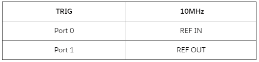 4.HDMI Connector Labeling
This is due to the combined functionality of the trigger signal sharing and the 10MHz reference clock synchronization through the HDMI cables. This can be observed in the pinout table of the HDMI cable, yellow marks the trigger lines green the in and out pins of the 10MHz reference clock.
To start daisy-chaining your PXI systems through the T&S Upgrade the recommended connection is the
Chassis 1 Port 1 to the
Chassis 2 Port0 (it is possible to connect the
Chassis 1 Port 0 to the Port 1 of
Chassis 2 but in this case, the Cassis 2 will be the 10MHz reference clock source). The trigger ports require that they connect to the opposite port on a remote chassis.
6. Valid Port Combinations
To connect
Chassis N+1 into the chain, connect
Chassis N's free port to the opposite port of
Chassis N+1. For example, if the free port on
Chassis N is Port 1 then connect it to
Chassis N+1 Port 0, if Port 0 is free on
Chassis N then connect it to Port 1 on
Chassis N+1. Repeat this for any number of chassis.
Additional useful information
- The cables are "hot-pluggable", changes in how they are connected are comprehended in real-time, and this should be reflected in NI-MAX.
- Every line is bidirectional and the trigger signals can go in or out on either port. The “In/Out” indications on the rear can be misleading in this way – they refer only to the 10MHz reference clock signal and have no meaning concerning the trigger lines.
Misuse Cases
- The system does not detect the invalid configurations, and so it will appear to the user that no chassis connect on the remote end of the cable, no damage will occur.
- Connecting chassis in a "circle" is not supported, but no damage will occur, measurements may be inaccurate or cards may not operate properly.
- Connecting a single chassis with an HDMI cable in a "loop-back" fashion (Chassis 1 Port 0 to Port 1) is not supported, but no damage will occur, measurements may be inaccurate or cards may not operate properly.
Configuring Trigger Routes with Software
Disclaimer: To be able to configure routes in LabVIEW you will need to install the NI-DAQmx driver .
Confirming Operation
With PXI Platform Services version 20.0, the T&S Upgrade will show up in NI-MAX with the following indicators when selecting the chassis:
- The Internal Oscillator is OXCO
- Visible TRIG/10MHz Port 0 Status and TRIG/10MHz Port 1 Status
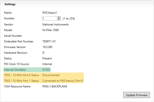
7. T&S Upgrade Indicators in NI-MAX
Another way to confirm that the extension is working is the following:
- Open LabVIEW.
- Create a new VI.
- Open the Block Diagram.
- On the Functions Palette go to Measure I/O>>NI DAQmx>>Advanced>>Signal Routing
- Place a DAQmx Connect Terminals VI on the block diagram.
- Create constants for the Source Terminal.
- Click on the drop-down menu of the terminal.
- Find the PFI ports of the extensions for all of your chassis.
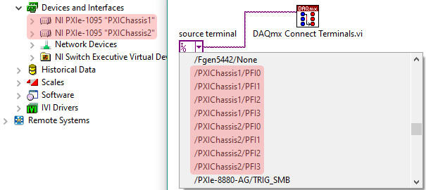
8. PFI Ports of the T&S Upgrade in LabVIEW
In the dropdown menu for the NI Terminal type, the DSUB PFI ports always show up when a T&S Upgrade is installed. When a chassis connect on the other end of the cable that isn’t part of the host system (i.e. a multi-host system), the “PortX/TrigY” endpoints show up.
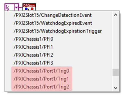
9. Trigger Lines in a Multi-Host System
These are hidden when MXI’ed chassis connect (i.e. a single-host system). This is because users are encouraged to route between modules or, when that isn’t possible, between chassis backplanes. Routing infrastructure will determine a path across the cables.
Setting Up Trigger Routes
It is possible to implement the trigger signal routes in different ways. However it is recommended to create a complete route from where a signal originates to where it is consumed, in one step; where that isn’t possible, do it in the fewest, largest portions possible is preferred.
The trigger signal route implementation types are the following based on their lifetime:
Dynamic (a.k.a "Task-Based" or "Session-Based") - Dynamic reservation/routing/deallocation is on the fly within a user program based upon National Instruments APIs such as NI-DAQmx. Route or Reservation(R&R) is scoped to the lifetime of the process or session used to create it. When the program or session closes, the R&Rs are undone as well. Example: Trigger routes created with the
DAQmx Trigger VI are deleted with the cleaning up of their
DAQmx tasks.
Static - Static reservation pre-allocates a trigger line to prevent its configuration by a user program. This R&R stick around permanently, even past system reboots, until the user deliberately does something to undo them. Example: Trigger routes created in the PXI Trigger Pane in MAX.
The T&S Upgrade supports only dynamic trigger route implementation:
"National Instruments drivers such as NI-DAQmx must be used to route triggers between chassis dynamically; routing triggers between chassis using static routes defined in MAX is not supported."
10. Quote From the Manual of the PXIe-1095
If possible use dynamic routes, this is because the dynamic route declaration binds the route to the operation that’s leveraging it, providing the best usability and maximizing our ability to manage routing resources automatically, including cleaning them up.
Implementation
As a first step, make sure that the trigger settings of the PXI chassis are set to "Dynamic" for all the trigger busses that you are intending to use for cross chassis triggering. You can set this in NI-MAX by clicking on the PXI chassis and locating the Triggers tab on the bottom of the window. With this the routes are left unconfigured and available for National Instruments products to perform programmatic or automated routes to connect devices.
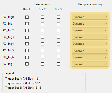
11. PXI Chassis Trigger Settings
Some NI drivers support implicit trigger routings, like NI-DAQmx, NI-DCPower, and NI-XNET (to see if your driver supports automatic route creation, please refer to the specific driver Help documentation).
Implicit - A concrete trigger source can be specified from different hardware/card which also can be in a different chassis. Example: The start trigger of the analog input on the DAQmx card (Dev1/ai/StartTrigger) can be configured for the trigger source in the "input terminal" of the DCPower Configure Trigger VI.
This is always supported for the above-mentioned drivers, including the case when the T&S Upgrade is used:
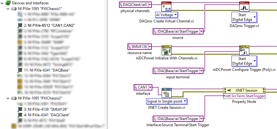
12. Dynamic Trigger Route Creation With Implicit Declaration
Many other drivers that are commonly used like NI-DMM, NI-RFSA, NI-RFSG, etc. use explicit trigger routing.
Explicit - The device can only specify the PXI trigger bus line to export or import a trigger signal to or from. Example: The NI-RFSG Export Signal VI can only specify the PXI_Trig0 line for trigger signal exportation.
The PXI trigger bus naming can differ for some of the drivers when using the trigger configuration VI, for example, PXI_Trig0, TTL0, RTSI 0, but all of them refer to the same PXI trigger lines from 0 to 7.
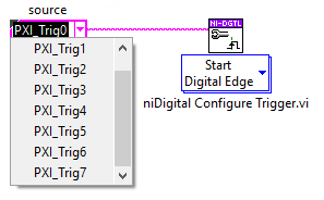
13. Trigger Configuration VI
When working with these drivers, it is possible to implement them in a dynamic route fashion with the help of the DAQmx Connect Terminals VI. This is needed since the majority of the drivers can only specify the PXI trigger bus to listen on for a trigger signal and cannot refer to a specific signal on a specific device, as seen before in case of the DAQmx, DCPower and XNET.
To connect together the intermediate connections between the PXI trigger busses, which were defined for the drivers, the DAQmx Connect Terminals VI should be used. In this case too, the cards can be in different chassis.
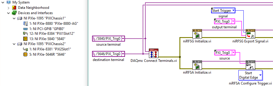
14. Partially Specified Route With DAQmx Connect Terminals VI
The defined terminals are connected together automatically by the DAQmx driver, so the programmer does not have to define each subpart of the signal path but this connection also has to be disconnected programmatically with the DAQmx Disconnect Terminal VI at the end of the measurement session.
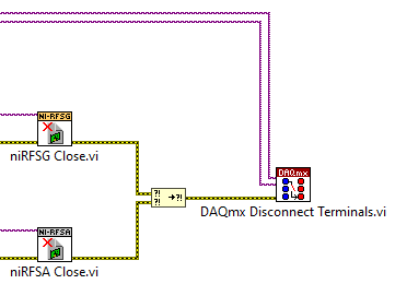
15. Disconnecting Trigger Route With DAQmx Disconnect Terminal VI