There are several methods to square up a voltage signal to make it TTL compatible. Here we are going to use the
Analog Trigger Circuitry of your E, S, M, or X series board.
With DAQmx, this method can be accomplished by routing digital signals internally. The Analog Comparison Event internal signal is a digital signal generated by an analog trigger and is easy to route. This signal can be made to follow your analog signal in a retriggerable way that will be a TTL digital signal emulating your analog waveform. This signal can be routed by following this procedure:
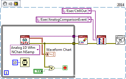
- Connect the route between the Analog Comparison Event signal and the counter output on your data acquisition board.
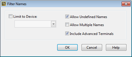
- To make this internal signal available, you must enable the Include Advanced Terminals checkbox in the Filter Names dialog box available from the right-click menu of the DAQmx Physical Channel constant.
3. Set up your DAQmx analog input task with an analog start trigger and hysteresis.
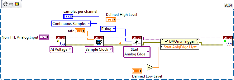
4. This start trigger will automatically result in the Analog Comparison Event comparison signal asserting every
time that your input signal rises above the Defined High Level
level trigger input. When your analog signal
goes below the Defined High Level trigger level minus the hysteresis level, this signal will deassert. Hence,
the
Start.AnlgEdge.Hyst hysteresis level is the Defined Low Level subtracted from the Defined High Level.
5. Read and clear the task, being sure to disconnect the routing you did in the first step
 Note: If your VI breaks during runtime after you have connected the routed signals but before you disconnected them, you must disconnect these signals manually. Additionally, resetting your hardware may be necessary.
Additional Information
In addition to using the analog circuity you could also apply a
Schmitt Trigger to your signal, or use an
Optically Isolated Digital I/O.
Schmitt TriggerA Schmitt trigger is a digital device used to convert an analog or slow transitioning digital signal to a fast transitioning digital signal. It essentially cleans up or squares up a signal by using a different threshold voltage for positive and negative-going transitions. This difference in threshold voltage for a positive-going (low to high) and negative-going (high to low) input signal is called hysteresis.
The operation of the Schmitt trigger is such that as the input voltage increases from 0 to 1.7 V the signal is considered low. When the signal reaches 1.7 V, the output of the trigger changes state to high. As the input voltage decreases from near 5 V to 0.9 V the signal is considered high. When the signal reaches 0.9 V, the Schmitt trigger changes state to low. This threshold difference window is the hysteresis window of the Schmitt trigger.
By using a hysteresis window, it is possible for the device to now convert analog signals to digital signals of the same frequency. The window also prevents glitches to be seen on slow moving (non-TTL compatible) digital signals. The 7414 integrated circuit is a typical Schmitt trigger inverter.
Optically Isolated DeviceThe third method to read or write a non-TTL digital signal is to use an optically isolated digital input-output (DIO) or transistor input-output (TIO) board. These boards can be used to interface with voltage levels as high as 60V. For performing DIO, the 6514, 6515, 6527, or 6528 can be used. If performing counter/timer operations, the 6624 board can be used.