This depends on what analog input module you have. The NI 9205, NI 9206, and NI 9775 are currently the only NI CompactDAQ modules that support analog triggering. You can use one of these modules in any slot on the chassis to configure an analog trigger for your task.
This task may include other modules that do not support analog triggering, but as long as there is at least one NI 9205, NI 9206, or NI 9775 included in the task, the entire task can have an analog trigger. As with other analog triggering, the trigger source specified needs to be the first channel in your scan list.
There is one exception when using the NI 9775 digitizer, in that you can only use analog triggering in finite acquisition and not continuous.
Let's have an example with the following hardware:
- NI 9205, NI 9206 analog input module or NI 9775 digitizer module
- cDAQ output module
- Multiple slot cDAQ chassis
Step 1: Connect and configure Hardware
- Insert the NI 9205/9206/9775 module and an output module into the cDAQ chassis and connect it to your computer. Find the hardware in NI MAX and take note of the module names given (in this example, cDAQ1Mod1).
- Wire the triggering analog signal into the NI 9205/9206/9775 module. It can be any of the analog input channels).
- Wire the output channel from the output module as required for your specific application (in this example, cDAQ1Mod2).
Step 2: Configure the hardware trigger using DAQmx
- In a LabVIEW VI, create an AI voltage task for the NI 9205/9206/9775 module and set the physical channel to that of your analog input signal.
- Set the AI task to trigger using an analog edge and specify the trigger source to be the same as the physical channel of the analog input signal.
- Create a new AO voltage task with the relevant physical channel.
- Set the AO task to trigger using a digital edge, and set the trigger source to be the cDAQ start trigger. In this example, it will be /cDAQ1/ai/StartTrigger. This is an internal channel along which a digital edge is sent when the NI 9205/9206/9775 module triggers.
- Ensure the AO task starts before the AI task.
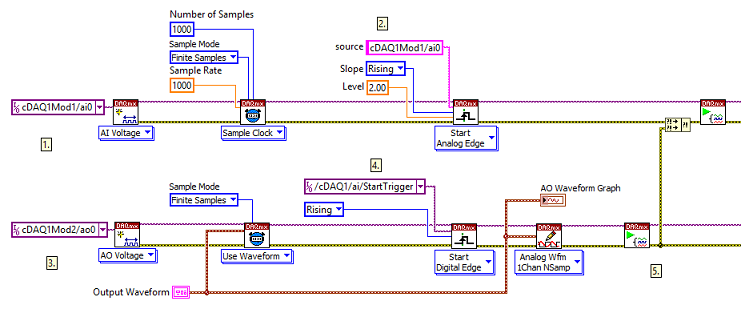
In this way, you are triggering the NI 9205/9206/9775 to send a separate digital edge down an internal cDAQ line that is used to trigger an output module to begin its task.
Additional Information
The NI 9205 and NI 9206 modules have a maximum sample rate of 250 kS/s, but the Analog Bandwidth (including analog triggers) is 370 kHz. This means you can connect and trigger from signals of higher frequencies than you can acquire. For example, you can trigger from a transient of up to 1.35 us (half period of a 370 kHz signal) without considerable attenuation, but past this frequency, it is necessary to account for the signal attenuation because the device will not trigger if the attenuated signal does not reach the configured trigger level.
This method will not work on a cDAQ-9172.
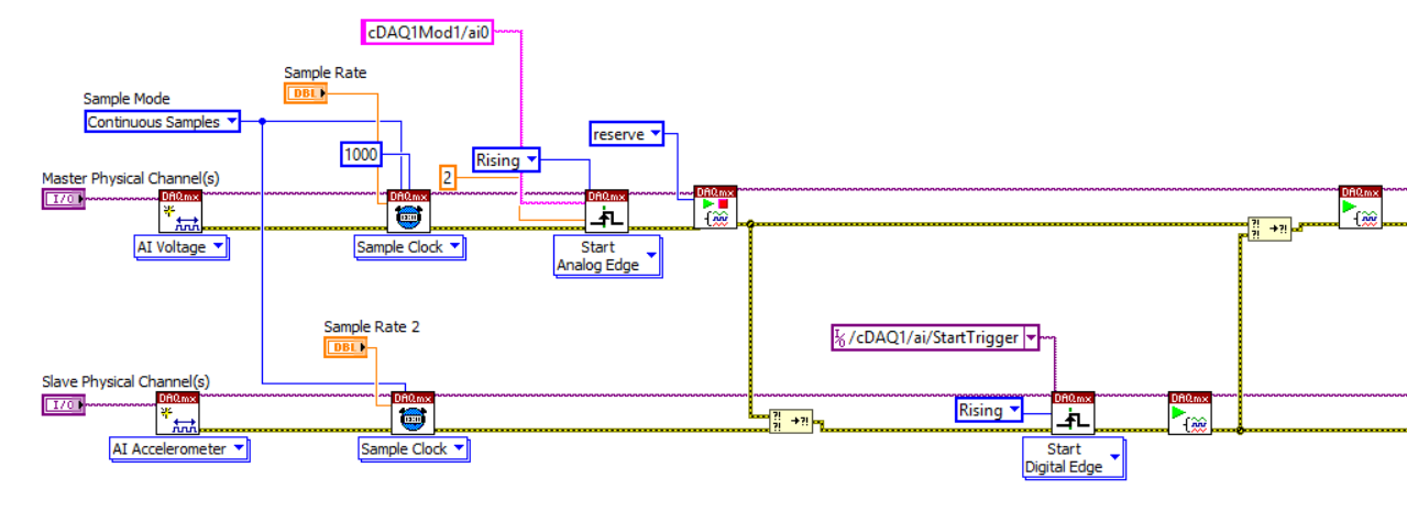
When this method is applied with two analog input tasks, the following error may appear:
Error -89131 occured at DAQmx Start Task.vi: 7220001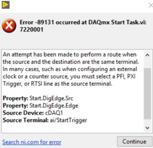
To avoid this error, place a
DAQmx Control Task.vi with the
Reserve action after the trigger function of the Master Task. To ensure that the analog trigger will be reserved before the Slave Task calls the digital trigger, add an additional
Merge Errors block after
DAQmx Control Task.vi.