This can be done by creating a DAQmx task for your type of measurement and then calibrating the channel within the task. When you calibrate a channel, you are increasing the accuracy of a measurement by compensating for errors due to cabling, wiring, or sensors. It should be noted that this type of calibration is only per task, and does not apply to the board. It is not a permanent calibration technique, and is not stored in EEPROM. For more information on permanent device calibration that is stored in EEPROM, refer to
Device Calibration.
You can achieve a similar effect by creating
a NI-DAQmx custom scale as well. To create a DAQmx task to measure and calibrate a channel, refer to the following steps:
- Create a new DAQmx Task in MAX.
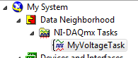
- Select My System»Data Neighborhood»NI-DAQmx Tasks»YourTaskName from the Configuration view in MAX.
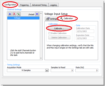
- Select Configuration»Calibration»Calibrate... in the NI_DAQmx Task view of your task.
- In the Channel Calibration Wizard fill in your name and when you wish this Calibration to expire and then select Next.
- Select the number of samples you wish to average and the sampling rate and select Next.
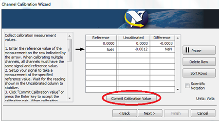
- When calibrating, make sure to select a value for each end of your device’s input range. You can select as many values as you want in between.
- In the Reference column, enter in the value that should be read in from the device. The value in the Uncalibrated column is the value the is currently being read from the device. When the Uncalibrated value is steady, select Commit Calibration Value. You will need to enter at least two values. If these values do not encompass the maximum and minimum value, it will ask you to use default values for the maximum and minimum when you proceed to the next stage.
- After you have all the Calibration values that you want set, select Next to go to the final step of the Channel Calibration Wizard. Here you can review your calibration curve and make sure there is adequate coverage. The Calibration Wizard uses linear interpolation between each Calibration Value you enter.
- Once you select Finish, the calibration is complete. The calibration data will automatically be applied when the task is used in LabVIEW or another development environment.
- To verify your calibration, select properties on the Calibration tab.
- Select the Values tab and then select Verify Calibration....
- Enter in your name when prompted and click Next.
- It will ask you if you want to select values to verify or if you want to use the same ones as you originally chose. Let the wizard guide you through the values you originally chose and select Next.
- In the Calibrated column, you will see the value currently being read from the device with the calibrated adjustments applied. When the Calibrated value is steady, select Commit Verification Value. When you have all the values set, select Finish.
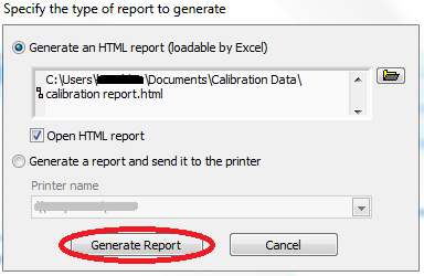
- Now the Values tab will show you the Reference values and associated Uncalibrated values and Calibrated values. To generate a report, select Generate Report.
- It will then ask you if you want to generate an HTML report or print it. After you have chosen, select Generate Report.
- The report will look like this:
Additional Information
This calibration applies only to the task that you've selected and does not carry across to other physical channels.
The Calibration Wizard can not be used programmatically in LabVIEW, but you can implement a similar type of task calibration using two methods: