National Instruments MID stepper drives support bipolar configuration. The following steps show how to connect for this use case.
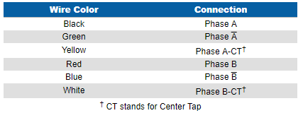
Phase A of the Vexta uses the black, yellow and green wires::
- Connect the black wire to the Phase A output and the green wire to the Phase A Bar output.
- The yellow wire is a center tap that can replace the green wire if you only need to use half of the available motor coils (half the torque) for Phase A.
Phase B uses the red, white and blue wires:
- Connect the red wire to the Phase B output and the blue wire to the Phase B Bar output.
- The white wire is the center tap that can replace the blue wire if you only need to use half of the available motor coils (half the torque) for Phase B.
Please see the
MID Power Drive User Guide or
Getting Started: P7000 Series Stepper Drives for more information on connecting stepper motors.
Additional Information
Many six-wire stepper motors, including Vexta Stepping Motors, can be operated both in unipolar and in bipolar modes. Unipolar motors typically have two coils per phase, one for each direction of magnetic field. Bipolar motors typically have one coil per phase, and current flows in both directions through this coil. Thus, of two motors of identical size, the bipolar would be able to produce twice as much torque, since at any given time, the unipolar motor is only using half of its windings.
Six-wire motors have three wires per phase. To connect for unipolar operation, the six wires are configured essentially as an H-bridge. In bipolar operation, the two middle leads are left disconnected, since current will be alternating at the source. To connect your motor, follow the information in the table below.

Table 1: Stepper Motor Wire Connection Color Coding